Network - PPP Modem
.
Network details
Type: Network
Name: PPP Modem
Status ESP32: NORMAL
Status ESP8266: .
GitHub: _NW005_PPP_modem.cpp
Maintainer: TD-er
Description
The PPP network interface allows to use one of many available GSM/GPRS/WCDMA/HSDPA/HSUPA/PSPA/LTE/4g modem modules to allow an ESPEasy node to be used literally “in the field”. When connected, a module offers a direct connection to the internet. Keep in mind this connection is like any other device behind a NAT router, thus no connection possible from the internet to the device itself.
N.B. There are exceptions to this, for example when using a custom service with your own SIM cards. These kinds of configurations are not tested, but also not actively disabled in ESPEasy.
All supported modules need to have an UART interface over which the ESP communicates using AT-commands.
Currently supported PPP modules (others may also work):
SIMCOM A76xx
SIMCOM A7070/A7000
BG96
SIM800 (obsolete)
Generic
The “Generic” option likely does work on most modules, however some specifics may not work.
Configuration
PPP modems need to communicate via a serial port. It is strongly adviced to use flow control where possible and use hardware serial (not software serial).
Most SIMCOM modules use 115200 as default baudrate, unless it is configured otherwise.
Make sure to have at least the reset pin of the PPP modem connected, or at the very least have the option to power cycle the modem. But this should be used only as last resort as the modem may take minutes to find a network after a power cycle.
LTE modules can draw a significant high current while connecting to the provider network. This can be upto 2 Ampere. So make sure either the module has ample capacitors (e.g. 330 uF … 470 uF) and preferrably also a soft-start circuit when enable power to the PPP modem.
Note
Never run these PPP modem modules without an antenna connected!
Network Settings
Route Priority
(ESP32 only)
When using multiple network interfaces, like WiFi, Ethernet or PPP LTE Modem, it must be made clear which interface should be used for new connections initiated from ESPEasy to some other host.
The connected network interface with the highest Route Priority is considered to be the default route.
Default Route Priority values are:
WiFi STA = 100
Ethernet = 50
PPP (LTE modem) = 20
WiFi AP = 10
Fallback Interface
(ESP32 only)
Note
The concept of a Fallback Interface is available on ESP8266, but only for WiFi AP. This is a special case, which is discussed here: Network - WiFi AP .
A network interface can be marked as “Fallback Interface”.
A fallback interface will only be scheduled to start when:
A non-fallback interface failed to connect.
Route Priority changed to a value which is less than the set priority for the fallback interface.
The scheduled delay to start the fallback interface is set as “Delay Startup” (see below).
A fallback interface will be stopped when there is a default route with a route priority higher than the set Route Priority of the fallback interface.
It is possible to set multiple interfaces as Fallback Interface. The fallback order can be tweaked using the Delay Startup and Route Priority.
N.B. Network interfaces which should be started at boot, should not be marked as Fallback Interface.
Example use cases
Disable fallback on the WiFi AP and have it active continuously, allowing other nodes/devices to use the ESP node to act as a router/gateway using “NAPT”.
Have WiFi STA set as fallback for Ethernet (or PPP for a LTE modem). When there is no connection via Ethernet (or PPP) you can try using WiFi STA as backup.
Have PPP (for connection via LTE) as fallback, so it will only be used if any of the other interfaces failed to get a connection.
Have Ethernet set to lowest startup delay, WiFi STA as fallback with longer startup delay and PPP as fallback with the longest startup delay. This way the preferred interface is Ethernet, WiFi the second and as last resort the LTE modem.
Delay Startup
For various reasons, it can be useful to not immediately start a network interface at boot. For example to reduce the power consumption as most network interfaces may draw significant more power for a short time when starting.
Another use case can be to check some sensor value before deciding to either start the network interface or enter deep sleep again.
The set value (in msec) is the delay from boot before starting the network interface.
Delay Startup for Fallback Interface
A Fallback Interface is not started at boot. The set Delay Startup is then used as delay to schedule starting the network interface. See “Fallback Interface” for more information.
Append Name to Hostname
(ESP32 only)
When multiple network interfaces may connect to the same network (e.g. WiFi STA and Ethernet), it can be useful to set different hostnames per network interface.
With this option checked, the network interface name as listed on the “Network” tab overview page will be appended to the hostname as used for that network interface.
For example on an ESPEasy node called “ESPEasy”, the WiFi STA interface will then use “ESPEasy-WiFi” as hostname.
This will be used in for example DHCP requests and when using mDNS.
Default setting is to have it disabled for WiFi STA and enabled for all other network interfaces.
Block Web Access
When checked, the ESPEasy web interface cannot be accessed via the IP-range of the network interface.
Note
The PPP Network Interface (ESP32-only) will have this checked by default, since you typically can’t access devices from the network of the mobile provider. If this is possible for some odd reason, you very likely would never want to allow this.
Enable IPv6
(ESP32 only)
Checking this checkbox, will allow the network device to use IPv6.
Collect Network Stats
(ESP32 only, not included in all builds)
Checking this checkbox, will allow to collect network statistics like:
Connected Station Count (AP only)
RSSI (WiFi, PPP)
TX Power (WiFi STA)
BER (Bit Error Rate, only on PPP)
TX Bytes
RX Bytes
Device Settings
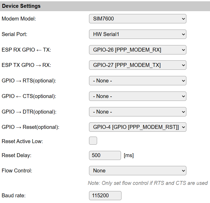
DTR pin
For SIMCOM A76xx modems, there is an emergency fallback option possible to regain access to the modem while the modem is in ‘data’ mode and not in ‘console’ mode.
ESPEasy does send the required AT-command AT&D1 right before starting the network connection to enable this fallback in the modem settings.
These PPP modems do have a console/command mode and a data mode. When entering AT commands, the modem must be pulled out of the data mode. However when the connection between the ESP and the modem got interrupted while the modem is still in data mode, it is impossible to regain access to the modem unless it is reset or power cycled. This may occur when the ESP crashes or reboots without properly terminating the PPP network connection, or when the serial link between the ESP and the modem is not using flow control (which is strongly suggested to use!).
Not all modem boards do have the DTR pin exposed. So make sure to either have the reset pin available, or as a last resort, have the option to power cycle the modem board. Power cycling should be considered as last resort to regain access to the modem, as it may take several minutes for a modem to get connected again after a power cycle.
Connection Settings
These settings are optional.
Note
These specific settings are stored in the file devsecurity.dat as these are specific to this device.
Access Point Name (APN)
The APN is like a default gateway for your device to connect to another network.
Typically the default APN as stored in the SIM card, or sent by the provider when setting up the connection, is just fine.
For some use cases, it may be required to set a specific APN, to override the pre-configured one stored in the SIM card.
A provider may offer several APNs, for example to connect to a specific customer network or to handle the traffic differently.
Whether or not this is even useful to change depends on the use case and the specific provider.
SIM Card Pin
A SIM card often has some 4-digit pin, which must be entered when powering up the device. If needed, the Pin number can be entered here.
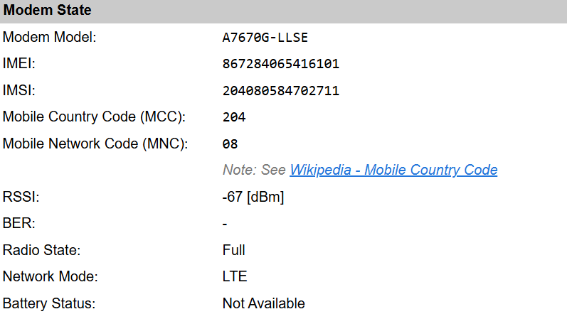
Modem State
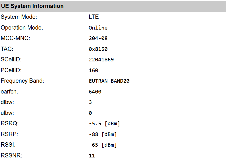
UE System Information
Useful AT commands
The command ppp,write,<AT-command> can be used to interact directly with the modem.
Note
The displayed output on the web interface often also includes the OK at the end. This is not part of the reply, but was originally printed on a separate line. However the way how these outputs are shown on the “Command Output” window, the extra newlines have been stripped from the response. The log on the serial port will output these on separate lines.
ppp,write,ATIExample output:+GCAP: +CGSM,+FCLASS,+DSppp,write,AT+IPR=?Listing supported baud rates:+IPR: (300,600,1200,2400,4800,9600,19200,38400,57600,115200,230400,460800,921600,1842000,3686400)ppp,write,AT+CSPN?Show the SIM card carrier string:+CSPN: "Lebara",0ppp,write,AT+CCLK?Show local time as known by the modem:+CCLK: "70/01/01,00:53:53+00"
Example Devices
A7670E (DTR pin exposed, no RST pin)
A7670G (DTR pin exposed, no RST pin)
LilyGO T-PCIE V1.2 - AXP2101 - ESP32-WROVER - 16MB with modem: LilyGO TTGO T-PCIE A7670G
To use the last LilyGo T-PCIe v1.2 along with their A7670G modem combination as network interface #3, this config import can be used to get started:
networkimportconfig,3,`{"nwpluginID":5,"enabled":"true","route_prio":200,"fallback":"false","sn_block":"true","start_delay":1000,"en_ipv6":"false","serPort":4,"RX":26,"TX":27,"RTS":-1,"CTS":-1,"rst":4,"rst_act_low":"false","rst_delay":500,"baudrate":115200,"flowctrl":0,"phytype":2,"DTR":-1}`
Change log
Changed in version 2.0: …
added Major overhaul for 2.0 release.
Added in version 1.0: …
added Initial release version.