Command Reference
ESP Easy offers a set of commands to control hardware devices and provide some basic local control using rules. There are several ways to launch commands on ESP Easy:
Protocol |
Syntax |
Extra information |
|---|---|---|
HTTP |
http://<espeasyip>/control?cmd= |
Send commands over the HTTP protocol. |
MQTT |
<MQTT subscribe template>/cmd with payload: |
Send commands over the MQTT protocol. |
Serial (TTL) |
|
Send commands using serial (RX/TX). Just type the |
UDP |
SendTo,<unit nr>, |
Send commands from one ESP Easy unit to another. Setup UDP ESP Easy peer-2-peer controller first. |
Rules |
|
Internally within ESP Easy. Just enter the |
Commands are divided into several classes:
Internal Commands not related to plugins, controllers or notifications. Can be run from serial and rules engine
Rules Related to rules processing. Can be run from serial and rules engine
Plugin Commands specific for a plugin. Can be run from serial, rules engine, HTTP, MQTT
Special can be used from any source
Command a specific task for multiple instances of a plugin
When multiple tasks are assigned to run the same plugin, one may want to address a specific task to run the command.
In order to do so, prefix the command with the intended task name.
Either by using [<TaskName>]. or [<TaskNumber>]. (square brackets are optional) to address a specific instance.
N.B. This requires the plugin names to be unique (if the TaskName variant is used).
Examples:
[Display1].oledframedcmd,3,'Hello World'
[Display2].oledframedcmd,4,'From the other side'
This will display ‘Hello World’ on the 3rd line of the display with name ‘Display1’, and ‘From the other side’ on line 4 of the display named ‘Display2’.
[AC1].irsendac,{<some_json_to_control_AC>}
[AC2].irsendac,{<some_json_to_control_AC>}
This allows to control multiple IR controlled AC’s from one ESP.
Internal Commands
Commands handled by ESPEasy core. These are not part of a plugin.
TODO : Check commands M..Z and check for all commands whether the “class” is still valid.
Command |
Class |
Purpose / Syntax |
|---|---|---|
AsyncEvent |
Special |
Schedule an event, it’s possible to send a float value along as well. This is the same as a regular event, but it will not be executed immediately. Instead it will be added to an event queue. Use this to keep rules execution times as short as possible. N.B. New values sent by a task will also be of this type. See event syntax below… |
AccessInfo |
Internal |
Show allowed IP range for the web interface.
Example output: |
Background |
Internal |
Process background tasks.
|
Build |
Internal |
Get or set build information. This will not be stored, so only valid until reboot.
Example output: |
ClearAccessBlock |
Internal |
Clear allowed IP range for the web interface for the current session.
See also
|
ClearPassword |
Internal |
Clear the password of the unit.
See also
|
ClearRTCram |
Internal |
Clear all (cached) data from the RTC memory. This data is persistent as long as the node is powered and thus survives a reboot or crash.
|
ClearSdkWifi |
Internal |
ESP8266 only (added: 2022/11/11) Clear the 12k SDK WiFi partition at the end of the flash memory. This data is used by the ESP8266 Arduino SDK to keep some persistent WiFi settings. When WiFi is performing badly, it might be useful to clear this section. Especially when switching SDK build revisions, like when switching between regular builds and ‘beta’ or ‘alt.WiFi’ builds. Please reboot after clearing this partition. See also
|
ClearWifiRFcal |
Internal |
ESP8266 only (added: 2022/11/11) Clear the 4k RFcal partition near the end of the flash memory. This data is used by the ESP8266 Arduino SDK to keep store WiFi RF calibration data. When WiFi is performing badly, it might be useful to clear this section. Especially when switching SDK build revisions, like when switching between regular builds and ‘beta’ or ‘alt.WiFi’ builds. Another reason to clear the RF calibration is when initial RF calibration was done with a different power supply, or when WiFi performs badly after placing the ESP in a different enclosure which may de-tune the antenna. Please reboot after clearing this partition. See also
|
Config |
Internal |
Remote config of a task. This allows for actually change the config as stored in the settings for a task. The syntax is like Right now only the Later other config options might be added, like Example for the task named ‘VoltageLevel’: |
ControllerDisable |
Internal |
Disable a controller. This will not save the settings, but if the settings get saved anyway the controller will remain disabled at reboot.
|
ControllerEnable |
Internal |
Enable a controller. (Only possible when a protocol is assigned to the controller index) This will not save the settings, but if the settings get saved anyway the controller will remain enabled at reboot.
|
DateTime |
Internal |
Get or set the date and time (optional). Usage: Examples:
Time source will be set to |
Debug |
Internal |
Change Serial port debug level
|
Dec |
Internal |
Decrement the value of variable n (1..INT_MAX), or use a variable name, by 1 or an optional value.
Examples:
See also |
DeepSleep |
Internal |
Switch the node to deep sleep. Max sleep time depends on library version and differs from roughly 71 minutes (4294 sec.) to 3h46 for ESP8266, and up to 8 years (281474976 sec.) on ESP32 (theoretically). If you specify a Min sleep time of 0, you’ll have to wake the device yourself by pulling RST to GND. If you specify a negative sleep time value, the maximum will be applied.
|
Delay |
Rules |
Delay rule processing. Warning: Do not use this as it may cause all kinds of issues.
|
DNS |
Internal |
Get or set DNS configuration.
Example output: |
DST |
Internal |
Get or set Daylight Saving Time.
Example output: |
EraseSDKwifi |
Internal |
Erase WiFi settings that may have been stored in the SDK wifi settings area.
|
Event |
Special |
Create an event, it’s possible to send a float value along as well. See event syntax below… |
ExecuteRules |
Internal |
Execute the rules in a specific file on the file system.
|
FactoryReset |
Internal |
Reset config to factory default. Caution, all settings will be lost! changed 2024-08-10: Renamed
|
Gateway |
Internal |
Get or set the gateway configuration
Example output: |
HiddenSSID |
Internal |
Get or set the Include Hidden SSID setting
Example output: |
I2Cscanner |
Internal |
Run I2C scanner to find connected I2C chips. Output will be sent to the serial port.
Added: 2024-06-14:
With the optional debug argument Added: 2024-06-14: Scan is performed at the Low I2C speed configured (default 100 kHz). When having an I2C multiplexer configured, all channels of the multiplexer will also be scanned. Example output: >i2cscanner
Standard I2C bus
I2C : Found 0x3c
I2C : Found 0x40
I2C : Found 0x5a
>i2cscanner,1
Standard I2C bus
I2C : Error 2 at 0x01
I2C : Error 2 at 0x02
I2C : Error 2 at 0x03
...
I2C : Error 2 at 0x3f
I2C : Found 0x40
I2C : Error 2 at 0x41
...
I2C : Error 2 at 0x7e
I2C : Error 2 at 0x7f
|
Inc |
Internal |
Increment the value of variable n (1..INT_MAX), or use a variable name, by 1 or an optional value.
Example:
See also |
IP |
Internal |
Get or set IP address
Example output: |
Latitude |
Internal |
Set the latitude for the unit, that’s used when calculation the sunrise/sunset times.
Range: -90 .. 90 (decimal, negative is southern hemisphere) When no argument is provided, the current setting is shown. See also |
Let |
Internal |
Set the value of variable n (1..INT_MAX), or use a variable name.
Examples:
See also |
Load |
Internal |
Load (reload) the stored settings.
|
LogEntry |
Internal |
Add string to log
When a |
LogPortStatus |
Internal |
Display status information about all ports
|
Longitude |
Internal |
Set the longitude for the unit, that’s used when calculation the sunrise/sunset times.
Range: -180 .. 180 (decimal, negative is west of the prime meridian) When no argument is provided, the current setting is shown. See also |
LoopTimerSet LoopTimerSet_ms |
Rules |
Start a sequence of timed events
The 3rd value is optional and can be used to set a fixed number of loops. When possible, try using the On a typical setup, calling Please note, the execution time in the rules may differ, but as long as a loop timer is used, the scheduled time to run is always a fixed interval from when it was set. (even when a timer interval was missed) The
See also N.B. the timernr is shared between |
LoopTimerSetAndRun LoopTimerSetAndRun_ms |
Rules |
Set a Loop-Timer using If a Useful for setting a keep-alive timer, and also send the initial keep-alive signal immediately. |
meminfo |
Internal |
Will send summary of struct sizes to the serial port.
Example output: 4306250 : Info : Command: meminfo
SecurityStruct | 593
SettingsStruct | 1228
ExtraTaskSettingsStruct| 472
DeviceStruct | 12
|
meminfoDetail |
Internal |
Will enable extra detailed information on the internal structure of the settings file. This is displayed graphically in the system info page. This state is not stored, so only active until reboot. A detailed summary is also sent to the serial port.
|
Name |
Internal |
Set the name of the unit
|
Notify |
Rules |
Trigger a notification. Requires the notifier at the numbered index (1..3) to be enabled. Optionally include the message body (quoted) and subject (quoted) to be passed. NB: The buzzer doesn’t support a message body or subject. Syntax: Example:
|
NTPHost[,<host-name_or_ip>] |
Internal |
Set the name of the NTP-host
|
OWScan |
Internal |
Scan for & list 1-wire (One Wire = OW) devices on a GPIO pin. Syntax: If no separate TX pin is provided, the RX pin will be used as the TX pin too, as is the normal behavior for 1-wire communication. The separate TX pin is used on a Shelly device when adding the Shelly Temperature add-on (RX = GPIO-0 and TX = GPIO-3). Example: >owscan,5
01-6e-56-8c-01-00-00-84 [DS1990A]
|
Password |
Internal |
Set the password of the unit.
See also
|
PostToHTTP |
Rules |
Syntax format 1:
Post a command to other network device via HTTP using the http
Syntax format 2:
For both syntax formats:
Syntax examples:
Example using syntax format 1:
Example using syntax format 2:
On completion of the command, the returned status code can be handled in a generated event, f.e. See also: Added: 2023-01-15 |
PostToHTTPS |
Rules |
Like NB: No certificate validation is done! |
Provision,Config |
Internal |
Fetch
|
Provision,Security |
Internal |
Fetch
|
Provision,DevSecurity |
Internal |
Fetch
|
Provision,Notification |
Internal |
Fetch
|
Provision,Provision |
Internal |
Fetch
|
Provision,Rules |
Internal |
Fetch
|
Provision,Firmware |
Internal |
Fetch a new firmware binary, and flash it on the unit, as configured in the Provisioning configuration (see Settings Archive)
|
Publish |
Rules |
Send command using MQTT broker service. The ‘Will Retain’ option as configured in the MQTT Controller settings is used. Uses the first enabled MQTT Controller.
|
PublishR |
Rules |
Send command using MQTT broker service, with the MQTT ‘Will Retain’ flag enabled. Uses the first enabled MQTT Controller.
|
PutToHTTP |
Rules |
Syntax format 1:
Send a command to another network device via HTTP using the http
Syntax format 2:
For both syntax formats:
Syntax examples:
Example using syntax format 1:
Example using syntax format 2:
On completion of the command, the returned status code can be handled in a generated event, f.e. See also: Added: 2023-04-17 |
PutToHTTPS |
Rules |
Like NB: No certificate validation is done! |
Reboot |
Internal |
Reboot the ESP
|
Reset |
Renamed |
changed 2024-08-10: Renamed |
Reset Flash Write Counter |
Internal |
Reset flash write to zero.
|
Rules |
Internal |
Rules enabled (1) or rules disabled (0)
|
Save |
Internal |
Save config to persistent flash memory
|
ScheduleTaskRun |
Internal |
(Added: 2023/02/10)
Schedule a call to
|
SendTo |
Rules |
Send command to other ESP (using UDP)
If the |
SendToHTTP |
Rules |
Send command to other network device using HTTP (not HTTPS!)
Syntax:
Example:
On completion of the command, the returned status code can be handled in a generated event, f.e. |
SendToHTTPS |
Rules |
Like NB: No certificate validation is done! |
SendToUDP |
Rules |
Send command to other network device using UDP (non-ESP Easy units)
|
SendToUDPMix |
Rules |
Send command to other network device using UDP (non-ESP Easy units) and allow for binary data to be sent.
|
Settings |
Internal |
Show settings on serial terminal
|
Subnet |
Internal |
Get or set the network subnet setting
Example output:
|
Subscribe |
Rules |
Subscribes to a specific topic using MQTT broker service
|
TaskClear |
Internal |
Delete the given task/device
|
TaskClearAll |
Internal |
Delete ALL task/device
|
TaskDisable |
Internal |
Disable a task. This will not save the settings, but if the settings get saved anyway the task will remain disabled at reboot.
|
TaskEnable |
Internal |
Enable a task. (only possible when a plugin is assigned to the task) This will not save the settings, but if the settings get saved anyway the task will remain enabled at reboot.
|
TaskRun |
Internal |
Run/excecute the given task/device, use to manually force an update/read of the task.
|
TaskRunAt |
Internal |
(Added: 2023/02/10)
Run/excecute the given task/device, use to manually force an update/read of the task.
Difference with Note Not all plugins do immediately produce a result, as some re-schedule themselves after the measurement has completed. Those will not keep this suggested timestamp. Dummy tasks do keep this suggested timestamp. Not all controllers will use the suggested timestamp. The Cache Controller does use this. N.B. This does not schedule to run a task in the future, but only provides a suggested timestamp to hand over to the controller(s).
For scheduling to run a task, see
|
TaskValueSet |
Rules |
Set values on a Dummy Task (device).
|
TaskValueSetAndRun |
Rules |
Set values on a Dummy Task (device) and run/execute the task/device, to manually force an update/read of the task.
|
TaskValueSetDerived |
Rules |
Define a Derived value for a task. A Derived value is an extra value, available for the device, that can return a calculated result, based on any variable available in the system.
Examples: In
In other places, like rules, and in Display tasks, you can now use Derived values can be shown on the Devices overview page, and included in the |
TaskValueSetPresentation |
Rules |
Define a presentation formula for a task. The presentation result will be used when displaying the devices values on the Devices overview page, and as the
Note NB: The Presentation set using this command doesn’t alter the values retrieved by using the Examples:
Here we define a presentation formula for all values, including the Derived values, of the BME task. If the Show derived values checkbox is enabled, it could look like this for a BME280 task: 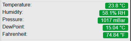
Change presentation from numeric to text: For another device, there is a numeric presentation of a climate system that should be presented in readable text: In
And also:
This uses the 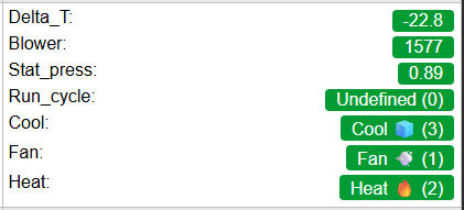
Derived values for Cool, Fan and Heat have also been added as illustration. This example also shows that the Derived values (all below Run_cycle) are presented in alphabetic order, not case-sensitive. Present extra values for Sysinfo plugin: In
This adds the Derived value for InternalTemp, that maps to the existing Get Config value The formula for 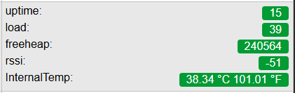
A simplified version of |
TimerPause |
Rules |
Pause a timer
|
TimerResume |
Rules |
Resume a paused timer
|
TimerSet TimerSet_ms |
Rules |
Start a timed event
See also N.B. the timernr is shared between |
TimeZone |
Internal |
Get or set the TimeZone
Example output:
|
UdpPort |
Internal |
Set the udp port
|
UdpTest |
Internal |
Send a test message to an udp port, for <count> number of times
|
Unit |
Internal |
Set the unit number
|
UseNTP |
Internal |
Get or set the status of NTP (Network Time Protocol)
Example output:
|
WdConfig |
Internal |
Configure external Watchdog device
|
WdRead |
Internal |
Read from external Watchdog device
|
WifiAPKey |
Internal |
Change AP WPA key
|
WifiAllowAP |
Internal |
Uncheck the setting to prevent starting AP when unable to connect to a network.
|
WifiAPMode |
Internal |
Force the unit into AP mode or turn AP mode off.
|
WifiConnect |
Internal |
Connect to configured wireless network
|
WifiDisconnect |
Internal |
Disconnect from wireless network
|
WifiKey |
Internal |
Change WPA key for primary WiFi
|
WifiKey2 |
Internal |
Change WPA key for secondary WiFi
|
WifiScan |
Internal |
Scan Wireless networks
|
WifiSSID |
Internal |
Change SSID to connect as primary WiFi
|
WifiSSID2 |
Internal |
Change SSID to connect as secondry WiFi
|
WifiSTAMode |
Internal |
Force the unit into STA mode.
|
Event command
The event command is a special command used to trigger an event. This event can then be acted upon from the rules. You can send 0..4 event values along with the event.
An event will be executed immediately if its origin demands a state update. For events which do not need to be executed immediately, we have the AsyncEvent, which is added to an event queue. This queue is processed 10 times per second, one event at a time.
Try to use AsyncEvents where possible, to keep rules processing times low.
Event / Info |
|---|
The event (triggered by any of the launch ways) will make the unit publish a message. Rules example on SingleEvent do
Publish,%sysname%/Info,A single event has been triggered!
endon
|
The event value Rules example on SingleValue do
Publish,%sysname%/Info,An event has been sent (%eventvalue%)!
endon
|
The event value Rules example on Multi do
if %eventvalue4%=99
TaskValueSet,12,1,[%eventvalue1%+%eventvalue2%]
else
TaskValueSet,12,1,[%eventvalue3%-%eventvalue2%]
endif
endon
|
GPIO Commands
Internal GPIO
Internal GPIO handling NORMAL CLIMATE
Supported hardware: Relay, Servo motor
Command (GPIO/Value) |
Extra information |
|---|---|
GPIO: 0 … <max supported GPIO pin> State: 2 (HIGH-Z, input) 1 (HIGH, output) 0 (LOW, output) |
Basic on/off.. We can control a pin with simple http URL commands. To change the pin to high or low steady output. Setting GPIO to 2 means that it will be able to detect low level relays (with high impedance, Z). |
GPIO: 0 … <max supported GPIO pin> |
Toggle on/off.. Toggle the current (output) state of the given GPIO pin. When executed, it changes the pin mode to output, for output-capable GPIO pins. |
GPIO: All GPIO pins with output capabilities State: 1/0 Duration low/high: 1 … 999 S Nr of Repeats: |
To send a *long* pulse to a certain pin.. A long pulse is basically the same as the plain pulse. Duration is defined in seconds, which makes it more suitable for longer duration. This command is not blocking, but will send 2 events to start and stop the pulse. This may have some variation depending on the system load of the module. Variation is typically up-to 10 msec, but may be up-to a second, depending on active plugins and controllers performing blocking operations. Changed: 2022/10/15
Example: |
GPIO: All GPIO pins with output capabilities State: 1/0 Duration low/high: 1 … 15000 msec Nr of Repeats: |
To send a (non blocking) *long* pulse to a certain pin. A Changed: 2022/10/15
Example: |
GPIO: All GPIO pins with output capabilities State: 1/0 Duration: 0 … 1000 msec |
To send a *short* pulse to a certain pin. Example to send an active high (1) pulse on GPIO 14 for 500 mSeconds. Pulse duration is in milliseconds. State is 1 or 0. N.B. this is a blocking call, meaning no other actions will be performed during the pulse. |
ESP8266 GPIO: 0 … 15 ESP32 GPIO: All GPIO pins with output capabilities Duty: 0 … 1023 Duration: 100 … 15000 msec (optional) Frequency: 100 … 40000 Hz (optional) |
To set a certain PWM level. If you have set a certain GPIO to a PWM level and want to use it as a regular HIGH/LOW pin you need to reset by setting the PWM level to 0. Duration (in msec) parameter will create a fading. Value of 0 will not set a duration. Frequency (in Hz) will be set to 1000 Hz when not given. Frequencies above 30 kHz are not stable and will likely crash the ESP. |
ESP8266 GPIO: 0 … 15 ESP32 GPIO: All GPIO pins with output capabilities Servo: 1/2 Position: -180 … 180 (see warning below) |
To control a servo motor.
Builds before 2020/11/22 only supported a maximum of 2 servos. Later builds allow more and no longer need the Warning Most servos are not able to turn full 360°! Normally the servos are able to go from -90° to 90°, some rare servos do allow for -135° to 135°. A position value of 9000 will stop the PWM signal. This can be useful to save energy on servos which do not need power to remain at the same position. |
GPIO: 0 … <max supported GPIO pin> |
To monitor a GPIO state. By the use of the command you will receive events when the GPIO state of that pin is changed from 1 to 0 and from 0 to 1. |
GPIO: 0 … <max supported GPIO pin> |
To cancel the monitor of a GPIO state. By the use of the command you will stop receiving events when the GPIO state of that pin is changed from 1 to 0 and from 0 to 1. |
GPIO: 0 … <max supported GPIO pin> |
Returns the status of a pin. By the use of the command you will receive the status of the relevant pin. |
External MCPGPIO
Command (MCPGPIO/Value) |
Extra information |
|---|---|
MCPGPIO: 1 … 128 State: 2 (HIGH-Z, input) 1 (HIGH, output) 0 (LOW, output) -1 (OFFLINE, disconnected) |
Basic on/off.. We can control a pin with simple http URL commands. To change the pin to high or low steady output. Setting MCPGPIO to 2 means that it will be able to detect low level relays (with high impedance, Z). |
MCPGPIO: 1 … 128 |
Toggle on/off.. Toggle the current (output) state of the given MCPGPIO pin. When executed, it changes the pin mode to output. |
MCPGPIO: 1 … 128 State: 1/0 Duration: 1 … 999 S |
To send a *long* pulse to a certain pin.. A long pulse is basically the same as the plain pulse. Duration is defined in seconds, which makes it more suitable for longer duration. This command is not blocking, but will send 2 events to start and stop the pulse. This may have some variation depending on the system load of the module. Variation is typically up-to 10 msec, but may be up-to a second, depending on active plugins and controllers performing blocking operations. |
MCPGPIO: 1 … 128 State: 1/0 Duration: 10 … 15000 msec |
To send a *long* pulse to a certain pin.
A |
MCPGPIO: 1 … 128 State: 1/0 Duration: 0 … 1000 msec |
To send a *short* pulse to a certain pin. Example to send an active high (1) pulse on MCPGPIO 14 for 500 mSeconds. Pulse duration is in milliseconds. State is 1 or 0. N.B. this is a blocking call, meaning no other actions will be performed during the pulse. |
MCPGPIO: 1 … 128 |
Returns the status of a pin. By the use of the command you will receive the status of the relevant pin. |
MCPGPIO: 1 … 128 |
To monitor a MCPGPIO state. By the use of the command you will receive events when the state of that pin is changed from 1 to 0 and from 0 to 1. |
MCPGPIO: 1 … 128 |
To cancel the monitor of a MCPGPIO state. By the use of the command you will stop receiving events when the state of that pin is changed from 1 to 0 and from 0 to 1. |
MCPGPIOfrom/MCPGPIOto: 1 … 128 (end has to be > start) |
To monitor a MCPGPIO state. By the use of the command you will receive events when the state of that pin is changed from 1 to 0 and from 0 to 1. |
MCPGPIO start/MCPGPIO end: 1 … 128 (end has to be > start) |
To cancel the monitor of a MCPGPIO state. By the use of the command you will stop receiving events when the state of that pin is changed from 1 to 0 and from 0 to 1. |
MCPGPIO start pin: 1 … 128
MCPGPIO end pin: 1 … 128 (end has to be > start)
value: 0 or 1
bitmask:
- if not present assume to operate in all pins
- if present is used as a mask (1=update, 0=do not update)
- pins are numbered from right to left (i.e. 87654321)
- if number of bit lower than number of pins, then padded with 0
- if number of bit higher than number of pins, then it’s truncated
|
Change the status of a pin for a given range applying the given mask
examples:
- mcpgpioRange,1,8,1 -> set pins 1 to 8 to 1
- mcpgpioRange,3,12,1 -> set pins 3 to 12 to 1
- mcpgpioRange,5,17,0 -> set pins 5 to 17 to 0
- mcpgpioRange,3,12,1,525 or mcpgpioRange,3,12,1,0b0100001101
mask = ‘0100001101’
write pattern after mask = ‘x1xxxx11x1’ where x indicates that the pin will not be changed
(only pin 1,3,4,9 will be changed)
- mcpgpioRange,3,12,1,973 or mcpgpioRange,3,12,1,0b1111001101
mask = 973 = ‘1111001101’
write pattern after mask = ‘1111xx11x1’ where x indicates that the pin will not be changed
|
MCPGPIO start pin: 1 … 128
MCPGPIO end pin: 1 … 128
write pattern: it’s a write pattern. Write 0 or 1.
- Example: use decimal number 15 (in binary is 00001111) to set to 1 pin 1,2,3 and 4 and to set to 0 pins 5,6,7,8
- if number of bit lower than number of pins, then padded with 0;
- if number of bit higher than number of pins, then it’s truncated.
bitmask:
- if not present assume to operate in all pins
- if present is used as a mask (1=update, 0=do not update)
- if number of bit lower than number of pins, then padded with 0
- if number of bit higher than number of pins, then it’s truncated
|
Change the status of a pin for a given range applying the given mask
examples:
- mcpgpioPattern,1,8,13
write pattern = ‘1101’ that will be padded as: ‘0000001101’
mask not present, assume mask = ‘1111111111’
- mcpgpioPattern,3,12,13
write pattern = ‘1101’ that will be padded as: ‘0000001101’
mask not present, assume mask = ‘1111111111’
- mcpgpioPattern,3,12,525
write pattern = 525 = ‘100001101’
mask not present, assume mask = ‘1111111111’
- mcpgpioPattern, 3, 12, 525, 973
write pattern = 525 = ‘100001101’
mask = 973 = ‘1111001101’
write pattern after mask = ‘1000xx11x1’ where x indicates that the pin will not be changed
|
MCPGPIO: 1 … 128
mode:
0 = OUTPUT
1 = INPUT PULLUP
2 = INPUT
|
To change the mode of an MCPGPIO pin. example: mcpMode,1,0 (set pin 1 as output)
|
MCPGPIO start pin: 1 … 128
MCPGPIO end pin: 1 … 128 (end has to be > start)
mode:
0 = OUTPUT
1 = INPUT PULLUP
2 = INPUT
|
To change the mode of an MCPGPIO range of pin. example: mcpModeRange,1,8,0 (set pin 1 to 8 as output)
|
External PCFGPIO
Command (PCFGPIO/Value) |
Extra information |
|---|---|
PCFGPIO: 1 … 128 State: 2 (HIGH-Z, input) 1 (HIGH, output) 0 (LOW, output) -1 (OFFLINE, disconnected) |
Basic on/off.. We can control a pin with simple http URL commands. To change the pin to high or low steady output. Setting PCFGPIO to 2 means that it will be able to detect low level relays (with high impedance, Z). |
PCFGPIO: 1 … 128 |
Toggle on/off.. Toggle the current (output) state of the given PCFGPIO pin. When executed, it changes the pin mode to output. |
PCFGPIO: 1 … 128 State: 1/0 Duration: 1 … 999 S |
To send a *long* pulse to a certain pin.. A long pulse is basically the same as the plain pulse. Duration is defined in seconds, which makes it more suitable for longer duration. This command is not blocking, but will send 2 events to start and stop the pulse. This may have some variation depending on the system load of the module. Variation is typically up-to 10 msec, but may be up-to a second, depending on active plugins and controllers performing blocking operations. |
PCFGPIO: 1 … 128 State: 1/0 Duration: 10 … 15000 msec |
To send a *long* pulse to a certain pin.
A |
PCFGPIO: 1 … 128 State: 1/0 Duration: 0 … 1000 msec |
To send a *short* pulse to a certain pin. Example to send an active high (1) pulse on PCFGPIO 14 for 500 mSeconds. Pulse duration is in milliseconds. State is 1 or 0. N.B. this is a blocking call, meaning no other actions will be performed during the pulse. |
PCFGPIO: 1 … 128 |
Returns the status of a pin. By the use of the command you will receive the status of the relevant pin. |
PCFGPIO: 1 … 128 |
To monitor a PCFGPIO state. By the use of the command you will receive events when the state of that pin is changed from 1 to 0 and from 0 to 1. |
PCFGPIO: 1 … 128 |
To cancel the monitor of a PCFGPIO state. By the use of the command you will stop receiving events when the state of that pin is changed from 1 to 0 and from 0 to 1. |
PCFGPIO start/PCFGPIO end: 1 … 128 (end has to be > start) |
To monitor a PCFGPIO state. By the use of the command you will receive events when the state of that pin is changed from 1 to 0 and from 0 to 1. |
PCFGPIO start/PCFGPIO end: 1 … 128 (end has to be > start) |
To cancel the monitor of a PCFGPIO state. By the use of the command you will stop receiving events when the state of that pin is changed from 1 to 0 and from 0 to 1. |
PCFGPIO start pin: 1 … 128
PCFGPIO end pin: 1 … 128 (end has to be > start)
value: 0 or 1
bitmask:
- if not present assume to operate in all pins
- if present is used as a mask (1=update, 0=do not update)
- pins are numbered from right to left (i.e. 87654321)
- if number of bit lower than number of pins, then padded with 0
- if number of bit higher than number of pins, then it’s truncated
|
Change the status of a pin for a given range applying the given mask
examples:
- pcfgpioRange,1,8,1 -> set pins 1 to 8 to 1
- pcfgpioRange,3,12,1 -> set pins 3 to 12 to 1
- pcfgpioRange,5,17,0 -> set pins 5 to 17 to 0
- pcfgpioRange,3,12,1,525 or pcfgpioRange,3,12,1,0b0100001101
mask = ‘0100001101’
write pattern after mask = ‘x1xxxx11x1’ where x indicates that the pin will not be changed
(only pin 1,3,4,9 will be changed)
- pcfgpioRange,3,12,1,973 or pcfgpioRange,3,12,1,0b1111001101
mask = 973 = ‘1111001101’
write pattern after mask = ‘1111xx11x1’ where x indicates that the pin will not be changed
|
PCFGPIO start pin: 1 … 128
PCFGPIO end pin: 1 … 128 (end has to be > start)
write pattern: it’s a write pattern. Write 0 or 1.
- Example: use decimal number 15 (in binary is 00001111) to set to 1 pin 1,2,3 and 4 and to set to 0 pins 5,6,7,8
- if number of bit lower than number of pins, then padded with 0;
- if number of bit higher than number of pins, then it’s truncated.
bitmask:
- if not present assume to operate in all pins
- if present is used as a mask (1=update, 0=do not update)
- if number of bit lower than number of pins, then padded with 0
- if number of bit higher than number of pins, then it’s truncated
|
Change the status of a pin for a given range applying the given mask
examples:
- pcfgpioPattern,1,8,13
write pattern = ‘1101’ that will be padded as: ‘0000001101’
mask not present, assume mask = ‘1111111111’
- pcfgpioPattern,3,12,13
write pattern = ‘1101’ that will be padded as: ‘0000001101’
mask not present, assume mask = ‘1111111111’
- pcfgpioPattern,3,12,525
write pattern = 525 = ‘100001101’
mask not present, assume mask = ‘1111111111’
- pcfgpioPattern, 3, 12, 525, 973
write pattern = 525 = ‘100001101’
mask = 973 = ‘1111001101’
write pattern after mask = ‘1000xx11x1’ where x indicates that the pin will not be changed
|
PCFGPIO: 1 … 128
mode:
0 = OUTPUT
1 = INPUT PULLUP
2 = INPUT
|
To change the mode of an PCFGPIO pin. example: pcfMode,1,0 (set pin 1 as output)
|
PCFGPIO start pin: 1 … 128
PCFGPIO end pin: 1 … 128
mode:
0 = OUTPUT
1 = INPUT PULLUP
2 = INPUT
|
To change the mode of an PCFGPIO range of pin. example: pcfModeRange,1,8,0 (set pin 1 to 8 as output)
|
Ringtone Internal GPIO
Internal GPIO handling NORMAL CLIMATE
Supported hardware: Buzzer (RTTTL), Piezo element, Speaker (Ringtones etc.)
Command (GPIO/Value) |
Extra information |
|---|---|
ESP8266 GPIO: 0 … 16 ESP32 GPIO: All GPIO pins with output capabilities Tone: 20 … 13000 Hz Duration: 100 … 15000 msec |
ESP8266: You should try to use GPIO 12…16 since these generally aren’t used. The recommended tone range is 20 Hz … 13 kHz. Up-to 40 kHz should be possible to generate, but will be inaudible for humans. Frequencies above 30 kHz are not stable and will likely crash the ESP. Duration is set in ms. N.B. tones with a duration less than 50 msec will be blocking. Longer duration will use the scheduler, which may cause some fluctuations in the duration. |
ESP8266 GPIO: 0 … 16 ESP32 GPIO: All GPIO pins with output capabilities Value: d=<duration>,o=<octave>,b=<tempo>,<notes…> |
ESP8266: You should try to use GPIO 12…16 since these generally aren’t used by ESP internal functions. Value can be defined like <name_of_melody:duration,octave,beat,notes….> For example:
Since 2023-09-15: The Also, the previous implementation may not have stopped sound correctly after playing a song, but as this has been corrected, so there is no longer a need to turn off the GPIO after playing a song. |
Task Value Stats Commands
(Added: 2022/07/11) For task values with “Stats” enabled, one can call commands on this statistical data.
Commands on “Stats” data:
bme.resetpeaksReset the recorded “max” and “min” value of all task values of the task called “bme”.bme.clearsamplesClear the recorded historic samples of all task values of the task called “bme”.
Plugin based commands
Besides the internal commands there’s also plugin specific commands.
These can only be handled when the specific plugin is included in the ESPEasy build (and the plugin is assigned to an enabled task)
P003 Generic - Pulse counter
Command (GPIO/Value) |
Extra information |
|---|---|
legacy method:
|
Reset the counters (pulse counter and total counter) of P003 Pulse Counter. When using multiple instances of Pulse Counter tasks, use a prefix to address the right one. E.g. The command will also trigger a call to |
legacy method:
|
Set the value of the total count of P003 Pulse Counter. When using multiple instances of Pulse Counter tasks, use a prefix to address the right one. E.g. A call to set the counter total will also trigger a call to N.B. The set value is the internal value, so any present formula will be processed after this value is set. |
Optional subcommands:
|
Initiate a single log entry with statistical information of current PULSE counter parameters (only if PULSE mode type is being used. Cf. special chapter about The <subcommand> is executed AFTER writing to logfile, so you see the result of the reset in consecutive loggings. The When using multiple instances of Pulse Counter tasks, use a prefix to address the right one. E.g. N.B. Note that this single log entry is done, when Log Level is set to |
P007 Analog input - PCF8591
Command |
Extra information |
|---|---|
Value: 0..255 |
The value is linearly scaled from 0V to Vref. Vref is often the same as VCC for the chip, but can sometimes be configured using a potentiometer on the board. Only available if Enable Analog output (AOUT) is enabled. |
P009 Switch Input - MCP23017
Command (MCPGPIO/Value) |
Extra information |
|---|---|
MCPGPIO: 1 … 128 State: 2 (HIGH-Z, input) 1 (HIGH, output) 0 (LOW, output) -1 (OFFLINE, disconnected) |
Basic on/off.. We can control a pin with simple http URL commands. To change the pin to high or low steady output. Setting MCPGPIO to 2 means that it will be able to detect low level relays (with high impedance, Z). |
MCPGPIO: 1 … 128 |
Toggle on/off.. Toggle the current (output) state of the given MCPGPIO pin. When executed, it changes the pin mode to output. |
MCPGPIO: 1 … 128 State: 1/0 Duration: 1 … 999 S |
To send a *long* pulse to a certain pin.. A long pulse is basically the same as the plain pulse. Duration is defined in seconds, which makes it more suitable for longer duration. This command is not blocking, but will send 2 events to start and stop the pulse. This may have some variation depending on the system load of the module. Variation is typically up-to 10 msec, but may be up-to a second, depending on active plugins and controllers performing blocking operations. |
MCPGPIO: 1 … 128 State: 1/0 Duration: 10 … 15000 msec |
To send a *long* pulse to a certain pin.
A |
MCPGPIO: 1 … 128 State: 1/0 Duration: 0 … 1000 msec |
To send a *short* pulse to a certain pin. Example to send an active high (1) pulse on MCPGPIO 14 for 500 mSeconds. Pulse duration is in milliseconds. State is 1 or 0. N.B. this is a blocking call, meaning no other actions will be performed during the pulse. |
MCPGPIO: 1 … 128 |
Returns the status of a pin. By the use of the command you will receive the status of the relevant pin. |
MCPGPIO: 1 … 128 |
To monitor a MCPGPIO state. By the use of the command you will receive events when the state of that pin is changed from 1 to 0 and from 0 to 1. |
MCPGPIO: 1 … 128 |
To cancel the monitor of a MCPGPIO state. By the use of the command you will stop receiving events when the state of that pin is changed from 1 to 0 and from 0 to 1. |
MCPGPIOfrom/MCPGPIOto: 1 … 128 (end has to be > start) |
To monitor a MCPGPIO state. By the use of the command you will receive events when the state of that pin is changed from 1 to 0 and from 0 to 1. |
MCPGPIO start/MCPGPIO end: 1 … 128 (end has to be > start) |
To cancel the monitor of a MCPGPIO state. By the use of the command you will stop receiving events when the state of that pin is changed from 1 to 0 and from 0 to 1. |
MCPGPIO start pin: 1 … 128
MCPGPIO end pin: 1 … 128 (end has to be > start)
value: 0 or 1
bitmask:
- if not present assume to operate in all pins
- if present is used as a mask (1=update, 0=do not update)
- pins are numbered from right to left (i.e. 87654321)
- if number of bit lower than number of pins, then padded with 0
- if number of bit higher than number of pins, then it’s truncated
|
Change the status of a pin for a given range applying the given mask
examples:
- mcpgpioRange,1,8,1 -> set pins 1 to 8 to 1
- mcpgpioRange,3,12,1 -> set pins 3 to 12 to 1
- mcpgpioRange,5,17,0 -> set pins 5 to 17 to 0
- mcpgpioRange,3,12,1,525 or mcpgpioRange,3,12,1,0b0100001101
mask = ‘0100001101’
write pattern after mask = ‘x1xxxx11x1’ where x indicates that the pin will not be changed
(only pin 1,3,4,9 will be changed)
- mcpgpioRange,3,12,1,973 or mcpgpioRange,3,12,1,0b1111001101
mask = 973 = ‘1111001101’
write pattern after mask = ‘1111xx11x1’ where x indicates that the pin will not be changed
|
MCPGPIO start pin: 1 … 128
MCPGPIO end pin: 1 … 128
write pattern: it’s a write pattern. Write 0 or 1.
- Example: use decimal number 15 (in binary is 00001111) to set to 1 pin 1,2,3 and 4 and to set to 0 pins 5,6,7,8
- if number of bit lower than number of pins, then padded with 0;
- if number of bit higher than number of pins, then it’s truncated.
bitmask:
- if not present assume to operate in all pins
- if present is used as a mask (1=update, 0=do not update)
- if number of bit lower than number of pins, then padded with 0
- if number of bit higher than number of pins, then it’s truncated
|
Change the status of a pin for a given range applying the given mask
examples:
- mcpgpioPattern,1,8,13
write pattern = ‘1101’ that will be padded as: ‘0000001101’
mask not present, assume mask = ‘1111111111’
- mcpgpioPattern,3,12,13
write pattern = ‘1101’ that will be padded as: ‘0000001101’
mask not present, assume mask = ‘1111111111’
- mcpgpioPattern,3,12,525
write pattern = 525 = ‘100001101’
mask not present, assume mask = ‘1111111111’
- mcpgpioPattern, 3, 12, 525, 973
write pattern = 525 = ‘100001101’
mask = 973 = ‘1111001101’
write pattern after mask = ‘1000xx11x1’ where x indicates that the pin will not be changed
|
MCPGPIO: 1 … 128
mode:
0 = OUTPUT
1 = INPUT PULLUP
2 = INPUT
|
To change the mode of an MCPGPIO pin. example: mcpMode,1,0 (set pin 1 as output)
|
MCPGPIO start pin: 1 … 128
MCPGPIO end pin: 1 … 128 (end has to be > start)
mode:
0 = OUTPUT
1 = INPUT PULLUP
2 = INPUT
|
To change the mode of an MCPGPIO range of pin. example: mcpModeRange,1,8,0 (set pin 1 to 8 as output)
|
P011 Extra IO - ProMini Extender
Command |
Extra information |
|---|---|
|
Switch the pin to either low or high level output. |
|
Set the Analog pin (0..7) to the PWM level, where 0 = 0% and 255 = 100% of the VCC voltage the PME is running at. |
|
Switch the pin to either low or high level output, and after the duration has passed, return to the previous state. |
|
Switch the pin to either low or high level output, and after the duration (seconds!) has passed, return to the previous state. |
|
Report the current state/value for the pin selected. |
P012 Display - LCD2004
Command |
Extra information |
|---|---|
Value:
|
Using these commands, either from rules, via http or mqtt, the state of the display can be controlled. |
|
The <row> parameter corresponds with the same lines as the plugin configuration has. The <col> parameter sets the column the text will be displayed. The <text> parameter must be a single command parameter. Meaning, it must be wrapped in quotes when using a space or comma as text. If double quote characters are needed, wrap the parameter in single quotes or back quotes. All template notations can be used, like system variables, or reference to a task value. |
P019 Switch input - PCF8574
Command (PCFGPIO/Value) |
Extra information |
|---|---|
PCFGPIO: 1 … 128 State: 2 (HIGH-Z, input) 1 (HIGH, output) 0 (LOW, output) -1 (OFFLINE, disconnected) |
Basic on/off.. We can control a pin with simple http URL commands. To change the pin to high or low steady output. Setting PCFGPIO to 2 means that it will be able to detect low level relays (with high impedance, Z). |
PCFGPIO: 1 … 128 |
Toggle on/off.. Toggle the current (output) state of the given PCFGPIO pin. When executed, it changes the pin mode to output. |
PCFGPIO: 1 … 128 State: 1/0 Duration: 1 … 999 S |
To send a *long* pulse to a certain pin.. A long pulse is basically the same as the plain pulse. Duration is defined in seconds, which makes it more suitable for longer duration. This command is not blocking, but will send 2 events to start and stop the pulse. This may have some variation depending on the system load of the module. Variation is typically up-to 10 msec, but may be up-to a second, depending on active plugins and controllers performing blocking operations. |
PCFGPIO: 1 … 128 State: 1/0 Duration: 10 … 15000 msec |
To send a *long* pulse to a certain pin.
A |
PCFGPIO: 1 … 128 State: 1/0 Duration: 0 … 1000 msec |
To send a *short* pulse to a certain pin. Example to send an active high (1) pulse on PCFGPIO 14 for 500 mSeconds. Pulse duration is in milliseconds. State is 1 or 0. N.B. this is a blocking call, meaning no other actions will be performed during the pulse. |
PCFGPIO: 1 … 128 |
Returns the status of a pin. By the use of the command you will receive the status of the relevant pin. |
PCFGPIO: 1 … 128 |
To monitor a PCFGPIO state. By the use of the command you will receive events when the state of that pin is changed from 1 to 0 and from 0 to 1. |
PCFGPIO: 1 … 128 |
To cancel the monitor of a PCFGPIO state. By the use of the command you will stop receiving events when the state of that pin is changed from 1 to 0 and from 0 to 1. |
PCFGPIO start/PCFGPIO end: 1 … 128 (end has to be > start) |
To monitor a PCFGPIO state. By the use of the command you will receive events when the state of that pin is changed from 1 to 0 and from 0 to 1. |
PCFGPIO start/PCFGPIO end: 1 … 128 (end has to be > start) |
To cancel the monitor of a PCFGPIO state. By the use of the command you will stop receiving events when the state of that pin is changed from 1 to 0 and from 0 to 1. |
PCFGPIO start pin: 1 … 128
PCFGPIO end pin: 1 … 128 (end has to be > start)
value: 0 or 1
bitmask:
- if not present assume to operate in all pins
- if present is used as a mask (1=update, 0=do not update)
- pins are numbered from right to left (i.e. 87654321)
- if number of bit lower than number of pins, then padded with 0
- if number of bit higher than number of pins, then it’s truncated
|
Change the status of a pin for a given range applying the given mask
examples:
- pcfgpioRange,1,8,1 -> set pins 1 to 8 to 1
- pcfgpioRange,3,12,1 -> set pins 3 to 12 to 1
- pcfgpioRange,5,17,0 -> set pins 5 to 17 to 0
- pcfgpioRange,3,12,1,525 or pcfgpioRange,3,12,1,0b0100001101
mask = ‘0100001101’
write pattern after mask = ‘x1xxxx11x1’ where x indicates that the pin will not be changed
(only pin 1,3,4,9 will be changed)
- pcfgpioRange,3,12,1,973 or pcfgpioRange,3,12,1,0b1111001101
mask = 973 = ‘1111001101’
write pattern after mask = ‘1111xx11x1’ where x indicates that the pin will not be changed
|
PCFGPIO start pin: 1 … 128
PCFGPIO end pin: 1 … 128 (end has to be > start)
write pattern: it’s a write pattern. Write 0 or 1.
- Example: use decimal number 15 (in binary is 00001111) to set to 1 pin 1,2,3 and 4 and to set to 0 pins 5,6,7,8
- if number of bit lower than number of pins, then padded with 0;
- if number of bit higher than number of pins, then it’s truncated.
bitmask:
- if not present assume to operate in all pins
- if present is used as a mask (1=update, 0=do not update)
- if number of bit lower than number of pins, then padded with 0
- if number of bit higher than number of pins, then it’s truncated
|
Change the status of a pin for a given range applying the given mask
examples:
- pcfgpioPattern,1,8,13
write pattern = ‘1101’ that will be padded as: ‘0000001101’
mask not present, assume mask = ‘1111111111’
- pcfgpioPattern,3,12,13
write pattern = ‘1101’ that will be padded as: ‘0000001101’
mask not present, assume mask = ‘1111111111’
- pcfgpioPattern,3,12,525
write pattern = 525 = ‘100001101’
mask not present, assume mask = ‘1111111111’
- pcfgpioPattern, 3, 12, 525, 973
write pattern = 525 = ‘100001101’
mask = 973 = ‘1111001101’
write pattern after mask = ‘1000xx11x1’ where x indicates that the pin will not be changed
|
PCFGPIO: 1 … 128
mode:
0 = OUTPUT
1 = INPUT PULLUP
2 = INPUT
|
To change the mode of an PCFGPIO pin. example: pcfMode,1,0 (set pin 1 as output)
|
PCFGPIO start pin: 1 … 128
PCFGPIO end pin: 1 … 128
mode:
0 = OUTPUT
1 = INPUT PULLUP
2 = INPUT
|
To change the mode of an PCFGPIO range of pin. example: pcfModeRange,1,8,0 (set pin 1 to 8 as output)
|
P020 Communication - Serial Server
Command |
Extra information |
|---|---|
|
Using this command, either from rules, via http or mqtt, the text that is provided as content is completely sent to the serial port. No extra data is added, other than any (system) variables that are included, being replaced. |
|
This command will only send data to the network client, when there is an active connection. Using this command, either from rules, via http or mqtt, the text that is provided as content is completely sent to the network client. No extra data is added, other than any (system) variables that are included, being replaced. |
|
This command requires quotes to be used if spaces or commas are part of the content. Any data can be sent, even if it can not be typed in a text content, by specifying that as a separate argument:
|
|
This command is intended for testing as if data was received via serial. After placing the data in the buffer, the regular handling of that data is initiated. |
P021 Regulator - Level Control
Command |
Extra information |
|---|---|
Value: {Any valid numeric (float) value} Calculation: {A valid calculation, as can be used in Rules} |
Using this command, either from rules, via http or mqtt, the Set Level of the plugin can be changed. If the value differs from the currently set value, the settings are saved. |
Value: {Any valid numeric (float) value} Calculation: {A valid calculation, as can be used in Rules} |
Using this command, either from rules, via http or mqtt, the Hysteresis of the plugin can be changed. If the new value differs from the currently set hysteresis, the settings are saved. |
Value: {A valid numeric (bool) value } |
Using this command, either from rules, via http or mqtt, the remote control state of the plugin can be changed. When result is true and control mode is remote the Output will be set to active. When result is false local control algorithm is used. This value is never saved. |
Value: {0 or 1 } |
Using this command, either from rules, via http or mqtt, the remote control state of the plugin can be changed. If the value is 1 and control mode is remote the Output will be set to active. If the value is 0 local control algorithm is used. This value is never saved. |
|
Not a real command, but this plugin supports the |
|
Not a real command, but this plugin supports the |
P022 Extra IO - PCA9685
Command |
Extra information |
|---|---|
pcagpio: 0 … 15 value: 0 … 4096 duration: 100 … 15000 msec (optional) |
To set a certain PWM level. If you have set a certain pcagpio to a PWM level and want to use it as a regular HIGH/LOW pin you need to reset by setting the PWM level to 0. Duration (in msec) parameter will create a fading. Value of 0 will not set a duration. Next to the |
pcagpio: 0 … 15/all value: 0/1 |
To set 1 or all pins to on or off. The |
pcagpio: 0 … 15 value: 0/1 duration: 100 … 15000 msec resettimeout: (todo) when ‘auto’ is used, the reset is infinite. (todo) (optional) |
To set a pin temporarily to on or off for duration msec. with optional reset option. (todo) The |
frequency: 23 … 1500 |
Set the chip to the frequency specified, in the MODE2 setting configured. Next to the |
mode: 0 … 32 |
Set the MODE2 configuration in the chip (not in the Device Configuration), using the frequency setting as configured. |
P023 Display - OLED SSD1306
Command |
Extra information |
|---|---|
|
Turn the display off. |
|
Turn the display on. |
|
Remove all content from the screen. |
|
Write a line of text on the display, at the given position. |
P035 Communication - IR Transmit
Command |
Extra information |
|---|---|
irsend,<protocol>,<data>[,<bits>[,<repeats>]]Arguments:
<protocol>: Required. The IR protocol to use for sending the data.<data>: Required. The data to send out.<bits>: Optional. The number of bits of the protocol used. When using 0 (or not providing a value), the protocol-default will be used.<repeats>: Optional. How often should the data be transmitted. Many manual IR remotes repeat the same signal up to 3 times, and each protocol has a default setting for this parameter, that will be used when not specified. |
Send data out, using the protocol specified. The protocol and required data for a specific command can be obtained from f.i. a manual IR remote by using a TSOP4838 IR receiver and plugin P016: Communication - IR Receive (TSOP4838), retrieving the relevant data from the logs.
Supported protocols are available from the Protocols page at IRremoteESP8266 (external link)
|
irsendac,<{JSON-formatted-AC-command}>Argument:
<{JSON-formatted-AC-command}>: Required. A complete JSON string (single line) to control an airconditioner. |
Send a complete AC control command. These devices often require more complex commands and arguments, that can be 'carefully crafted' and sent using this command.
Documentation on how to craft these JSON commands can be found in this IRremoteESP8266 F.A.Q. answer (external link)
This JSON string does not have to be quoted if it contains spaces or commas, the entire text supplied is used as-is. It has to be valid JSON to be successfully processed, though.
This command is only available if the Extended AC support is included in the build. (This command is shown on the Device Configuration page when included)
|
P036 Display - OLED SSD1306/SH1106 Framed
Command |
Extra information |
|---|---|
Value:
|
OLED displays will age quite fast, so it is not adviced to run them continously at max brightness. Some displays do not accept all brightness levels and some also make a quite high pitch coil whine noise when running on some brightness levels. So different levels of brightness can also be of help on those displays. The display controller itself does support more brightness levels, but these are chosen to give noticable change in brightness levels and also to help in choosing the best values for the 2 brightness control registers. As there are 2 brightness control registers, there is some overlap in their range, but some combinations may lead to issues like coil whining noise or sometimes not even working displays as not all of these displays are wired to support both controls to be used. For the parameter of the user setting refer to the data sheet of the display.
An example for very low brightness with an user setting is |
|
The <line> parameter corresponds with the same lines as the plugin configuration has. The <text> parameter must be a single command parameter.
Meaning, it must be wrapped in quotes when using a space or comma as text.
A split token If double quote characters are needed, wrap the parameter in single quotes or back quotes. The updated line text is not stored in the settings itself, but kept in memory.
After a reboot the stored plugin settings will be used.
The line text can also be restored from the settings by the command All template notations can be used, like system variables, or reference to a task value. They will be interpreted once (while issuing the command) to generate the new line content. To use template notations that are to be reinterpreted each time before the line is displayed, the <line> parameter must be negative.
After receiving text this way, the frame where the text is placed is shown, if the setting for ‘Wake display on receiving text’ is checked. |
|
This command is to display a specific frame (aka page), or the next frame. When reaching the last frame, a ‘next’ (0) will display the first frame. The <framenr> parameter corresponds to the desired frame (1..<number of frames>) to display. The number of frames is determined by dividing the lines in use (at least one line in that frame with some data), by the number of Lines per Frame. So practically, the range is 1..3 when all lines are used and 4 Lines per Frame is set, or 1..12 if Line per frames is set to 1. The number of frames is updated if a frame would initially be empty, and an external source places text on a line of that frame (see above).
If scroll is set to When omitting <framenr>, or providing 0, the next frame is displayed. When the display is off, because a ‘Display Timeout’ is set and the timer has expired or it is turned off by the off command (see above), then it is turned on, and, when set, the timer is started again. |
|
This command changes the number of lines in each frame. When the next frame is to be displayed, the frames are recalculated and the sequence is restarted at the first frame.
If scroll is set to If Generate events for ‘Linecount’ is selected, a |
|
Set the global Left-align option for content off (0) or on (1). |
|
Set the global align option for content to centre (0), left (1) or right (2). |
|
Note: The use of |
|
Note: The use of |
|
If the <line> parameter is set to 0 all line contents will be restored from the settings. Otherwise the <line> parameter corresponds with the same lines as the plugin configuration has, and only the content of this line will be restored from the settings. |
|
The <speed> parameter corresponds with the line number of the scroll parameter of the settings (1=Very slow … 6=Ticker). After applying the new scroll speed the display restarts with the first page. |
P038 Output - NeoPixel (Basic)
Command Syntax |
Extra information |
|---|---|
NeoPixel,<led nr>,<red>,<green>,<blue>[,<brightness>] |
Set the LED to the provided R/G/B[/W] color value.
led nr: 1..<Led Count>
red: 0..255
green: 0..255
blue: 0..255
brightness: 0..255 (only applicable when using GRBW LEDs)
|
NeoPixelAll,<red>,<green>,<blue>[,<brightness>] |
Set all LEDs to the provided R/G/B[/W] color value.
|
NeoPixelLine,<start led nr>,<stop led nr>,<red>,<green>,<blue>[,<brightness>] |
Set a group of LEDs to the provided R/G/B[/W] color value.
Start LED nr and Stop LED nr should be within range 1..<Led Count>.
|
NeoPixelHSV,<led nr>,<hue>,<saturation>,<value> |
Set the LED to the provided H/S/V color value.
led nr: 1..<Led Count>
hue: 0..360
saturation: 0..100
value: 0..100
|
NeoPixelAllHSV,<hue>,<saturation>,<value> |
Set all LEDs to the provided H/S/V color value.
|
NeoPixelLineHSV,<start led nr>,<stop led nr>,<hue>,<saturation>,<value> |
Set a group of LEDs to the provided H/S/V color value.
Start LED nr and Stop LED nr should be within range 1..<Led Count>.
|
NeoPixelBright[,<brightness>] |
Set the level of display brightness, range: 0..255. If no brightness or 0 is provided, the Initial brightness setting is used.
The maximum brightness allowed is determined by the Maximum allowed brightness setting.
|
NeoPixelFor,<start led nr>,<stop led nr>,<increment>,<red>,<green>,<blue>[,<brightness>][,<clear>] |
Set a pattern of LEDs to the provided R/G/B[/W] color value.
Start LED nr and Stop LED nr should be within range 1..<Led Count>.
Increment must be <> 0, and can be negative if
<start led nr> > <stop led nr>.The <clear> argument, when provided with value 1, will clear the pixels that are not set to the requested color.
|
NeoPixelForHSV,<start led nr>,<stop led nr>,<increment>,<hue>,<saturation>,<value>[,<clear>] |
Set a pattern of LEDs to the provided H/S/V color value.
Start LED nr and Stop LED nr should be within range 1..<Led Count>.
Increment must be <> 0, and can be negative if
<start led nr> > <stop led nr>.The <clear> argument, when provided with value 1, will clear the pixels that are not set to the requested color.
|
P043 Output - Clock
Command Syntax |
Extra information |
|---|---|
config,task,<taskName>,SetTime,<timeIndex>,<timeString>[,<value>]Change the configuration of the plugin for the timeIndex provided:
|
This (generic) command allows to update the configuration. Warning Every time this command is used, the configuration is saved to flash storage. When changing this often, the flash memory may wear out quickly! Example command to use, when using
Will be stored like |
P048 Motor - Adafruit Motorshield v2
Command |
Examples |
|---|---|
Motornumber:
Action:
Speed: a value from 0-255 |
Turn on DC Motor, Direction: Forward. Speed: 99
Stopping the DC Motor:
|
Motornumber:
Action:
Steps: a value from 0-255 Stepsize:
|
Turn on DC Motor, Direction: Forward. Steps: 99
Stopping the DC Motor:
|
P049 Gases - CO2 MH-Z19
Command |
Explanation |
|---|---|
|
Sets the zero point of the sensor (in this case 400ppm) Reset to factory defaults Enables automatic baseline calibration Disables automatic baseline calibration |
P052 Gases - CO2 Senseair
Command (GPIO/Value) |
Extra information |
|---|---|
Value:
|
Used in tSense (K70) to set the relay to either |
P053 Dust - PMSx003 / PMSx003ST
Command |
Extra information |
|---|---|
|
Either pulls the |
|
Either pulls the |
|
If reset pin is set, the pin will be pulled down for 250 msec to reset the sensor. |
P059 Switch input - Rotary Encoder
Command Syntax |
Extra information |
|---|---|
encwrite,<count>> |
Set the Counter value, and generate an event for it, as if a pulse was received.
|
P065 Notify - DFPlayer-Mini MP3
Command |
Extra information |
|---|---|
Example:
|
Starts playing the nth file on the SD-card. Acceptable numbers 0..2999. |
|
Stops playing the current file immediately. |
Example:
|
Change the playback volume to the set level. Acceptable values 1..30. When 0 (or no argument) is provided, the max. volume will be set! Volume is also stored in the settings, but not saved untile either a |
Example:
|
Select the equalizer configuration. Acceptable values 0..5. 0 = Normal 1 = Pop 2 = Rock 3 = Classic 4 = Jazz 5 = Base |
Example:
|
Select the playback mode. Acceptable values 0..3. 0 = Repeat 1 = Folder repeat 2 = Single repeat 3 = Random NB: To have actual repeat playing a track, the NB2: This command does not work on all players, it may start a |
Example:
|
To set repeat mode. Default is off, acceptable values 0 or 1. 0 = Off 1 = On |
P067 Weight - HX711 Load Cell
Command |
Extra information |
|---|---|
|
Use the last measured value for Channel A as the Offset/Tare value. NB: Use |
|
Use the last measured value for Channel B as the Offset/Tare value. NB: Use NB2: When setting the Tare for both A and B channel, use |
P073 Display - 7-segment display
Command |
Extra information |
|---|---|
Example:
|
Displays a numeric value on the display, with 1 decimal position if space allows. |
Example:
|
To display the temperature measured by a BME280 sensor. By default includes a ° symbol, unless option ‘Hide ° for Temperatures’ is enabled. |
Example:
|
To display two temperatures measured, f.e. by a BME280 sensor and a DS18b20 sensor. Applicable for the MAX7219 and 74HC595 8 digit displays, as the other devices don’t have enough digits to show 2 temperatures. |
Example:
|
To display the time for a different time zone. Can also be used to f.e. set the next appointment time externally. |
|
To display a date. |
Examples:
|
To display a text on the display. Any variable can be used. Unsupported characters (like accented letters) will show as a space (empty digit). With the Scroll Text option disabled, the first n characters the display can show are displayed, if the Scroll Text option is enabled, longer texts will scroll from right to left across the display, at the set speed. |
|
Select a different font, either by name: |
Example:
|
To display any bit pattern on the display. The example shows each digit with a different segment on, including the dot/colon, and assuming either a MAX7219 - 8 digit, or Scroll Text enabled. See explanation on how the bits map to segments, below. |
|
Turn the display on. |
|
Turn the display off. |
|
Set the brightness to the provided level. |
|
Change the Display Output setting, available options:
|
P075 Display - Nextion
Command Syntax |
Extra information |
|---|---|
Task Name,'page.objname.txt="string"'Task Name,'page.objname.val=number' |
The Task Name is the user assigned Name for the Nextion Task. Avoid spaces, special characters and reserved words. The default name is NEXTION.
page.objname.txt is the field format for sending text strings to the Nextion display.
page.objname.val is the field format for sending integer values to the Nextion display.
The page. argument may be omitted if the Nextion object’s attribute is set as global.
|
Parameters |
HTTP Examples |
|---|---|
In these examples the assigned Task name is NEXTION. NEXTION,’page0.j1.txt=”Hello World”’ NEXTION,’page3.t0.val=777’ NEXTION,’page8.t_ram.txt=”System Time [%systime%]”’ |
Send Hello World to a text field on the display.
Send integer value -123 to a numeric field on the display:
Send a Switch plugin value to a numeric field on the display:
|
P076 Energy (AC) - HLW8012/BL0937
Command (GPIO/Value) |
Extra information |
|---|---|
Examples:
|
Will set the used calibration factors to some known current value.
For example, if the device using this sensor is plugged into mains power, it may report 200 Volt AC, while it actually is 229V.
So the value given to this command should then be The last two parameters are optional, but their position determines what unit it represents.
If the setting for current has to be updated, at least 2 parameters must be given of which the first must then be set to |
|
Will reset the calibration values used in the sensor’s library. |
P077 Energy (AC) - CSE7766
Command |
Extra information |
|---|---|
Examples:
|
Will set the used calibration reference factors to some known current value.
For example, if the device using this sensor is plugged into mains power, it may report 200 Volt AC, while it actually is 229V.
So the value given to this command should then be The last two parameters are optional, but their position determines what unit it represents.
If the setting for current has to be updated, at least 2 parameters must be given of which the first must then be set to |
|
Will reset the calibration values to the default values, causing auto-calibration. |
|
(Added: 2024-01-16) Will reset the CF-pulse counter. N.B. this also clears the kWh counter as it is derived from the CF-pulse counter. |
P078 Energy (AC) - Eastron SDMxxx Modbus
Command Syntax |
Extra information |
|---|---|
Eastron,PauseEastron,Resume |
Pause and Resume refer to the continuous reading of set registers of all connected Eastron modules.When changing a setting on a specific module, this background register reading must be temporarily halted by calling
Eastron,Pause first.All commands are case insensitive.
|
Eastron,SetBaud,<new_baudrate>[,<node_id>]Eastron,SetID,<new_id>[,<node_id>] |
The optional
<node_id> parameter indicates the current Modbus address. When not given, the default of address 1 is assumed.Valid node IDs are
1 ... 247.Call
Eastron,Pause before changing settings on the module.On some modules, like the SDM120, the user must press the button for 3 seconds to enter
-set- mode.After enabling the
-set- mode, these commands can be given and then the user must press the button for 3 seconds to store the changed settings.Changing ID is active immediately, thus the new ID must be used for commands given after changing the ID.
Change of baud rate is only active after the module is power cycled.
Allowed baud rates:
SDM120 / SDM230:
0 = 2400 baud (default)1 = 4800 baud2 = 9600 baud5 = 1200 baudSDM320 / SDM530Y:
0 = 2400 baud1 = 4800 baud2 = 9600 baud (default)5 = 1200 baudSDM630 / SDM72 / SDM72V2:
0 = 2400 baud1 = 4800 baud2 = 9600 baud (default)3 = 19200 baud4 = 38400 baudThe baud rate parameter can be given either as a value
0 … 5, or the exact (supported) baud rate.All commands are case insensitive.
|
P079 Motor - Wemos / Lolin Motorshield
Command Syntax |
Extra information |
|---|---|
WemosMotorShieldCMD,<Motornumber>,<Action>,<Speed>LolinMotorShieldCMD,<Motornumber>,<Action>,<Speed> |
The WemosMotorShieldCMD and LolinMotorShieldCMD command keywords are interchangeable.
The LolinMotorShieldCMD command keyword is available on mega-20200929 and later releases.
All commands are case insensitive.
|
Parameters |
HTTP Examples |
|---|---|
Motornumber:
Action:
Speed: 0-100 (Motor PWM Duty, 0% to 100%) |
Brake and Standby actions are available on mega-20200929 and later releases. Turn on DC Motor-A, Direction: Forward, Speed: 99
Stopping DC Motor-A:
Local Command Testing: Motor tests can be performed using the Command entry box found on ESPEasy device’s Tools page. For example: WemosMotorShieldCMD,0,Forward,99 |
P082 Position - GPS
Command |
Extra information |
|---|---|
|
Send u-blox specific command to put the GPS in backup mode. This turns off all parts of the GPS, except for the last known satellite trajectories. Use this to get a faster fix, compared to turning off the power to the GPS. In order to send a command to the GPS, the GPS RX pin must be connected. |
|
Send just any character to the GPS to wake it from backup mode (see This is u-blox specific. In order to send a command to the GPS, the GPS RX pin must be connected. |
P087 Communication - SerialProxy
Command |
Extra information |
|---|---|
|
Send out data via the configured serial port. |
|
This command requires quotes to be used if spaces or commas are part of the content. Any data can be sent, even if it can not be typed in a text content, by specifying that as a separate argument:
|
|
This command is intended for testing the regular expression and filtering. The sentence provided with this command is handed over for processing as if it was received via the serial port, so it will be processed and filtered, and an event will be generated if it’s matched. |
P088 Energy (Heat) - HeatpumpIR
Command |
Extra information |
|---|---|
model:
powerstate:
mode:
fan: a value from 0 to 5, 0 is auto speed temperature: temperature in degrees Celsius, 16-30 swingV: vertical swing position (not supported on most models) swingH: horizontal swing position (not supported on most models) |
Examples: Panasonic CKP on, automatic mode, automatic fan speed, 22 degrees C, automatic horizontal & vertical swing
For more examples, read the comments in the source code of P088_HeatpumpIR.ino |
P089 Communication - Ping
Command |
Extra information |
|---|---|
Examples:
Preferred syntax:
|
Set the Fails counter for the task. The deprecated syntax was instated before the generic task-specific command addressing, using |
P091 Switch input - Serial MCU controlled switch
Command |
Extra information |
|---|---|
|
Examples:
|
|
Examples:
|
|
Examples:
|
P093 Energy (Heat) - Mitsubishi Heat Pump
Command |
Description |
|---|---|
|
Value must be between |
|
Value = |
|
Value = |
|
Value = |
|
Value = |
|
Value = |
|
Value > |
P094 Communication - CUL Reader
Command |
Extra information |
|---|---|
|
Examples:
|
P095 Display - TFT ILI934x/ILI948x
Command Syntax |
Extra information |
|---|---|
This plugin allows dynamic configuration of the command-trigger. Available triggers are:
The default trigger is |
Some commands are postfixed with If one of the alternative Write Command trigger options is selected, then also the plugin specific commands change from |
tftcmd,on |
Switch the display on.
|
tftcmd,off |
Switch the display off. If the Backlight is connected and configured, that will also be turned off.
|
tftcmd,clear |
Clear the display, using the default background color. For clearing with a custom background color see the
<trigger>,clear[,<color>] command. |
tftcmd,backlight,<percentage> |
Set the level of backlight brightness, from 1..100%. Only applicable if a backlight pin is configured.
|
See also the AdafruitGFX Helper commands, below.
P098 Motor - PWM Motor
Command |
Extra information |
|---|---|
Move the motor to the Home position. |
Revert the motor until the limit switch A, aka Home, position is reached. This will cause the |
Move the motor to the End position. |
Move the motor forward until the limit switch B, aka End, position is reached. This will cause the |
Move the motor forward.
|
Move the motor a number of steps, or until the limit switch B, aka End, position is reached. If This will cause the |
Move the motor backward (reverse).
|
Move the motor a number of steps, or until the limit switch A, aka Home, position is reached. If This will cause the |
Stop the motor. |
Stop the motor moving (if, of course, it is moving). |
Move the motor to an absolute position. |
Move the motor to an absolute position. Expects to have the Home position defined, by moving to the Home position at least once. This will cause the |
P099 Touch - XPT2046 touchscreen on TFT display
Command |
Extra information |
|---|---|
Set the rotation to 0, 90, 180 or 270 degrees. The rotation angle should match with the display it is mounted on. Values:
(NB: I only have 1 display with a touchscreen mounted, and it is possible that mine is mounted 180 degrees rotated. It may be needed later to add a setting for this, we’ll see.) |
Examples:
|
Flip the rotation setting by 0 (default, value 0) or 180 degrees (numeric value > 0) |
Examples:
|
Enable a disabled touchobject by name. |
Examples:
|
Disable an enabled touchobject by name. |
Examples:
|
P101 Communication - Wake On LAN
Command Syntax |
Extra information |
|---|---|
Example 1:
WAKEONLAN,<Optional MAC>,<Optional IP>,<Optional Port>Example 2:
Task Name,<Optional MAC>,<Optional IP>,<Optional Port> |
When only one WOL task is assigned the WAKEONLAN and Task Name command keywords are interchangeable.
If multiple WOL tasks are assigned the user provided Task Name should be used as the command keyword.
Optional parameters will override the values entered in the WOL task’s configuration page. See examples below.
|
Optional Parameters |
HTTP Examples |
|---|---|
MAC Address:
IP Address:
Port Number:
|
Turn on family room Media Server (WOL task name MediaPlayer) using task’s default settings.
Turn on basement gaming PC using specific MAC address:
Turn on basement gaming PC using specific IP Address:
Turn on basement gaming PC using specific UDP port:
|
P104 Display - MAX7219 dot matrix
Command |
Extra information |
|---|---|
|
Clears a zone by number or the entire display. All Without a |
|
Update a zone, or all zones, with any updated content. Can be used instead of the Repeat (sec) option of a zone. Without a <zone> or All specified, the All action is executed. |
|
Set the size of the zone to |
|
Set the text displayed in the zone if it is of Content type Text.
|
|
Set the Content type for the specified zone, where
Will cause a reconfiguration of all zones. |
|
Change the alignment of the zone, 0 = Left, 1 = Center, 2 = Right. |
|
Change the Animation In setting for the zone. The |
|
Change the Animation Out setting for the zone. The |
|
Set the Speed factor for the indicated zone. Valid values 0..65535. |
|
Set the Pause delay in milliseconds for the indicated zone. Valid values 0..65535. |
|
Set the Font for the zone using a font ID. Valid font ID’s:
NB: Not all fonts are available in all builds, selecting an unsupported font will fail the command. Will cause a reconfiguration of all zones. |
|
Set the Layout for the indicated zone.
Will cause a reconfiguration of all zones. |
|
Set the Inverted state for the indicated zone.
Will cause a reconfiguration of all zones. |
|
Set the Special effect for the indicated zone.
Will cause a reconfiguration of all zones. |
|
Set the Offset for the indicated zone. Valid values 0..254. Will cause a reconfiguration of all zones. |
|
Set the Brightness level for the indicated zone. Valid values 0 (minimum)..15 (maximum brightness). |
|
Set the Repeat (sec) in seconds for the indicated zone. Valid values -1 (disabled)..86400 seconds (1 day). |
|
Set a zone with a Content type of Bar graph with 1 to 8 graph strings, to be displayed as bar graphs.
The graph string used for displaying 1 or more bar graphs is formatted like this: (square backets denoting optional arguments)
<value> The value to display. This is the only required argument. The usual <max value> The maximum expected value, defaults to 100 (treated as if it was a percentage). Can be negative if desired, but the min value should always be lower than the max value, but the values will be swapped if min value is larger than max value. <min value> The minimum expected value, defaults to 0. Negative value can be used, as well as > 0, the full bar graph will be scaled between the max and min values to fit in the zone. The <value>, <max value> and <min value> can be provided with decimal values (of type <direction> The default direction is 0, meaning from right to left (low value is on the right side, high value is on the left side), the ‘natural’ direction for the hardware, and can be changed to 1 for left to right display. <bartype> This can be 0, 1 or 2:
Most of these arguments are optional, but if a value is to be skipped, the default should be put in, f.e. Multiple graph strings can be used, these must be separated by a pipe symbol If the width of the bar graph is over 2, and the zero-point is visible on the display (max value > 0 and min value < 0), then the zero-point is marked on each bar by turning the outer pixels off, like this: | ********* |
| ********** | (a positive value)
| ********** |
| ********* |
| **** |
| ***** | (a negative value)
| ***** |
| **** |
^
+-- Zero-point
|
|
Draw individual dots on the display, in a row/column fashion, where an optional 0 can be added to turn a dot off, as the default is to turn a dot on. The row/column data doesn’t have to be quoted. The row and colum have to stay within the confines of the zone. Each zone is 8 dots high, and a multiple of 8 dots wide, depending on the number of modules in the zone. While drawing the dots, the zone is paused, so there is no animation effect while drawing the dots. Dots can be drawn independent of the type of content set for the zone, but once the original content is being updated or redrawn, the dots will be overwritten. |
P109 Display - ThermoOLED
Command Syntax |
Extra information |
|---|---|
Sub:
|
OLED displays will age quite fast, so it is not adviced to run them continously at max brightness. Some displays do not accept all brightness levels and some also make a quite high pitch coil whine noise when running on some brightness levels. So different levels of brightness can also be of help on those displays. This command is shared with Display - OLED SSD1306/SH1106 Framed, so when having both plugins enabled, the command has to be prefixed with the taskname and a periode, like |
|
Set the setpoint value, that the thermostat feature will try to maintain. |
|
Change the setpoint value down by 0.5 degrees, simulating a keypress on the Down button. This enables an alternative way to control the setpoint. If Manual mode is active, the timeout will be decreased by 5 minutes. |
|
Change the setpoint value up by 0.5 degrees, simulating a keypress on the Up button. This enables an alternative way to control the setpoint. If Manual mode is active, the timeout will be increased by 5 minutes. |
|
Change the mode to the next circular value in the 1, 2, 0 range, simulating a keypress on the Mode button. This enables an alternative way to control the thermostat mode. When Manual mode is selected, the timeout is by default set to 5 minutes, and after the timeout it returns to automatic mode. |
State:
Any other value: Turn off the heating. |
Set on the heating manually, either to |
Mode:
Timeout: A timeout for Manual mode in minutes. When no timeout is provided it will return to Automatic mode nearly immediately (~1 second). |
Set the thermostat mode. |
P115 Energy - MAX1704x
Command Syntax |
Extra information |
|---|---|
max1704xclearalert |
Clear the alert state. An alert event will only be sent when the alert state is set. Clearing it allows for new events to be set.
|
P116 Display - ST77xx TFT
Command Syntax |
Extra information |
|---|---|
This plugin allows dynamic configuration of the command-trigger. Available triggers are:
The default trigger is |
Some commands are postfixed with |
st77xxcmd,on |
Switch the display on.
|
st77xxcmd,off |
Switch the display off. If the Backlight is connected and configured, that will also be turned off.
|
st77xxcmd,clear |
Clear the display, using the default background color. For clearing with a custom background color see the
<trigger>,clear[,<color>] command. |
st77xxcmd,backlight,<percentage> |
Set the level of backlight brightness, from 1..100%. Only applicable if a backlight pin is configured.
|
See also the AdafruitGFX Helper commands, below.
P117 Gases - SCD30 CO2, Humidity, Temperature
Command Syntax |
Extra information |
|---|---|
scdgetabc |
Shows automatic calibration period in days, 0 = disable.
|
scdgetalt |
Shows altitude compensation configuration in meters above sea level.
|
scdgettmp |
Shows temperature offset in degrees C.
|
scdsetcalibration,<0|1> |
Set the sensor calibration mode to manual (0) or automatic (1).
The Device configuration setting is also updated, but not saved, when using this command.
About activating the Automatic Self Calibration (from the manual):
Continuous automatic self-calibration can be (de-)activated with the following command. When activated for the first time a period of minimum 7 days is needed so that the algorithm can find its initial parameter set for ASC. The sensor has to be exposed to fresh air for at least 1 hour every day. Also during that period, the sensor may not be disconnected from the power supply, otherwise the procedure to find calibration parameters is aborted and has to be restarted from the beginning. The successfully calculated parameters are stored in non-volatile memory of the SCD30 having the effect that after a restart the previously found parameters for ASC are still present. Note that the most recently found self-calibration parameters will be actively used for self-calibration disregarding the status of this feature. Finding a new parameter set by the here described method will always overwrite the settings from external recalibration (see chapter 1.3.7) and vice-versa. The feature is switched off by default.
To work properly SCD30 has to see fresh air on a regular basis. Optimal working conditions are given when the sensor sees fresh air for one hour every day so that ASC can constantly re-calibrate. ASC only works in continuous measurement mode. ASC status is saved in non-volatile memory. When the sensor is powered down while ASC is activated SCD30 will continue with automatic self-calibration after repowering without sending the command.
Warning Automatic Self Calibration is a tedious process, that at first run takes at least 7 days to complete, and requires the sensor to be in fresh air for at least 1 hour daily, during the self-calibration period. Note After enabling, and completing, ASC, do not apply a forced recalibration (FRC) as that will overwrite the carefully built up calibration. |
scdsetfrc,<co2_ppm> |
Set the sensor forced recalibration value. The
<co2_ppm> is validated to be between 400 and 2000 (as per the manual). When using this command, the sensor is switched to Manual Calibration, as Automatic Self Calibration overwrites this setting.Forced Re-Calibration instructions (from the manual):
Forced recalibration (FRC) is used to compensate for sensor drifts when a reference value of the CO2 concentration in close proximity to the SCD30 is available. For best results the sensor has to be run in a stable environment in continuous mode at a measurement rate of 2s for at least two minutes before applying the calibration command and sending the reference value. Setting a reference CO2 concentration by the here described method will always overwrite the settings from ASC (Automatic Calibration) and vice-versa. The reference CO2 concentration has to be within the range 400 ppm ≤ cref(CO2) ≤ 2000 ppm.
FRC value is saved in non-volatile memory, the last set FRC value will be used for field-calibration after repowering.
Warning Setting the sensor forced recalibration requires a reliable reference, in close vincinity of the sensor, to be useful. Note Setting a forced recalibration value will overwrite any earlier set, or automatically built via ASC, calibration. |
scdgetinterval |
Shows the current Measurement Interval of the sensor.
|
scdsetinterval,<interval> |
Set the Measurement Interval to
<interval> seconds. Factory default is 2 sec. Range from 2 to 1800 seconds.The Device configuration setting is also updated, but not saved, when using this command.
|
P118 Communication - Itho
Command Syntax |
Extra information |
|---|---|
itho,<state>(Command was
state, but that has been deprecated) |
Use the states in the table below to control the state of the fan. To pair the remote with the Itho fan use 1111 to join, or 9999 to leave/unjoin, respectively.
|
Examples:
HTTP control: http://ip/control?cmd=ITHO,1
MQTT conrol: mosquitto_pub -t /Fan/cmd -m ‘itho 1’ Here ‘Fan’ is the name of the plugin
Fan states
State |
Name |
Description |
|---|---|---|
0 |
Standby |
Itho ventilation unit on standby (not supported on most models) |
1 |
Low |
Itho ventilation to lowest speed |
2 |
Medium |
Itho ventilation to medium speed |
3 |
High |
Itho ventilation to high speed |
4 |
Full |
Itho ventilation to full speed (same as high on most models) |
13 |
Timer1 |
Itho to high speed with hardware timer (10 min) |
23 |
Timer2 |
Itho to high speed with hardware timer (20 min) |
33 |
Timer3 |
Itho to high speed with hardware timer (30 min) |
1111 |
Join with an ITHO ventilation unit that is waiting for join requests (first minutes after power-on) |
|
9999 |
Leave connection with an ITHO ventilation unit (maybe not supported on all models). Needs a new Join (1111) to be able to control a unit. |
|
100 |
Orcon standBy |
Orcon ventilation unit on standby |
101 |
Orcon low speed |
Orcon ventilation to lowest speed |
102 |
Orcon medium speed |
Orcon ventilation to medium speed |
103 |
Orcon high speed |
Itho ventilation to high speed |
104 |
Orcon auto speed |
Itho ventilation to auto speed (based on Humidity and/or CO2) |
110 |
Orcon Timer 0 |
Orcon ventilation unit on standby for 12*60 minutes |
111 |
Orcon Timer 1 |
Orcon ventilation to lowest speed for 60 minutes |
112 |
Orcon Timer 2 |
Orcon ventilation unit to medium speed for 13*60 minutes |
113 |
Orcon Timer 3 |
Orcon ventilation unit to high speed for 60 minutes |
114 |
Orcon Auto CO2 |
Itho ventilation to auto speed for 60 minutes (based on Humidity and/or CO2) |
Two special states exist: 1111 for a join command and 9999 for a leave/unjoin command, check the Itho manual on how to put your fain into pairing mode.
For Orcon the Unit ID remote 1 will be used as the spoofed sender ID
P123 Touch - I2C Touchscreens
P124 Output - I2C Multi Relay
Command Syntax |
Extra information |
|---|---|
multirelay,on,<channel> |
Switch on the relay at the channel given. Range is 1..8, but limited to the number the plugin is configured for.
|
multirelay,off,<channel> |
Switch off the relay at the channel given. Range is 1..8, but limited to the number the plugin is configured for.
|
multirelay,set,<channel_bitmap> |
Switch on and off according to the bitmap provided, in 8..1 order. The bitmap can be given in decimal (
nn, 1-3 digits, 0 to 9), hexadecimal (0xnn, 1 or 2 digits, 0 to f) or binary (0bnnnnnnnn, 1 to 8 digits, 0 or 1) notation. |
multirelay,get,<channel> |
Get the current state of the requested channel (checked for being in range 1 to the number of relays configured), and put that in the Channel and Get values, so it will be available to rules or a configured controller.
|
multirelay,loop,0|1 |
Disable or enable getting the next channel state on every Interval read. Corresponds to the Loop Channel/Get on read option in the device settings, but does not check/uncheck that setting.
|
P126 Output - Shift registers (74HC595)
Command Syntax |
Extra information |
|---|---|
ShiftOut,Set,<pin>,<0|1> |
Set
<pin> to the state provided. Pin numbers start at 1 and continue up to no. of chips * 8. The shift registers are updated immediately |
ShiftOut,SetNoUpdate,<pin>,<0|1> |
Set
<pin> to the state provided. Pin numbers start at 1 and continue up to no. of chips * 8. The shift registers are not updated. See ShiftOut,Update command. |
ShiftOut,Update |
Update the current buffered state to the shift registers.
|
ShiftOut,SetAll,[chip:][width:]<value>... |
Set the addressed chip(s) with the value provided. Values should be max. 32 bit. Chip starts at 1 by default, and width is 4 by default. Shift registers are updated immediately.
To select a single chip with 8 bits of data, use a
width of 1, use 2 for updating 2 adjacent chips with a 16 bit value, etc. |
ShiftOut,SetAllNoUpdate,[chip:][width:]<value>... |
See
ShiftOut,SetAll command, but without immediate update to the shift registers. See ShiftOut,Update command to set the output to the shift registers. |
ShiftOut,SetAllLow |
Switch all shift register outputs to off (low). Immediately updates the shift registers.
|
ShiftOut,SetAllHigh |
Switch all shift register outputs to on (high). Immediately updates the shift registers.
|
ShiftOut,SetChipCount,<chip count> |
Change the number of chips configured. Will adjust the configuration immediately, and set in Device configuration, but not store the setting, use the
save command for storing the setting.When increasing the number of chips, the extra outputs will all be set to low/off.
|
ShiftOut,SetOffset,<chip offset> |
Change the
Offset for display configuration setting. Does not save the setting, use the save command for storing the setting. |
ShiftOut,SetHexBin,<0|1> |
Change the Values display (Off=hex/On=Bin) setting to on (1) or off (0). Does not save the setting, use the
save command for storing the setting. |
P127 Gases - CO2 CDM7160
Command Syntax |
Extra information |
|---|---|
cdmrst |
Resets the sensor. (Documentation does not state what is actually reset, but it is assumed that the Altitude setting is reset to it’s default value 0.)
|
P128 Output - NeoPixel (BusFX)
Command Syntax |
Extra information |
|---|---|
NB: The |
|
For brevity the
nfx command is used here. |
|
Led count == Number of pixels.
|
|
nfx,off[,fadetime[,delay]] |
Switches the stripe off, using the optional fadetime and delay timings (milliseconds).
|
nfx,on[,fadetime[,delay]] |
Restores the last state of the stripe, active before a
nfx off command was applied, using the optional fadetime and delay timings (milliseconds). |
nfx,dim[,dimvalue] |
Set the brightness of the stripe, range
0 to 255 (max. brightness), set to 0 when not specified. If the provided dimvalue exceeds the configured Max brightness configuration setting, or is negative, it is ignored (invalid command). |
nfx,line,<startpixel>,<endpixel>,<color> |
Light up the pixels from startpixel (range: 1..number of pixels) to endpixel (range: number of pixels..startpixel) with the specified color. Color is to be specified in a hex RRGGBB value.
|
nfx,hsvline,<startpixel>.<endpixel>,<hue>,<saturation>,<brightness> |
Light up the pixels from startpixel (range: 1..number of pixels) to endpixel (range: number of pixels..startpixel) with the specified hsvcolor values.
|
nfx,one,<pixel>,<color> |
Light up 1 pixel (range: 1..number of pixels) with the specified color. Color is to be specified in a hex RRGGBB value.
|
nfx,hsvone,<pixel>,<hue>,<saturation>,<brightness> |
Light up 1 pixel (range: 1..number of pixels) with the specified hsvcolor values.
|
nfx,all,<color>[,fadetime[,delay]]nfx,rgb,<color>[,fadetime[,delay]]nfx,fade,<color>[,fadetime[,delay]] |
Light up all pixels with the specified color, using the optional fadetime and delay timings (milliseconds). Color is to be specified in a hex RRGGBB value.
For the
all and rgb subcommands, the delay is set to 0 if not specified. When using the fade subcommand, a previously set delay is used. |
nfx,hsv,<hue>,<saturation>,<brightness>[,fadetime[,delay]] |
Light up all pixels with the specified hsvcolor values, using the optional fadetime and delay timings (milliseconds).
Delay is set to 0 if not specified.
|
nfx,colorfade,<startcolor>,<endcolor>[,startpixel[,endpixel]] |
Change the color for all or specified start- to end-pixels, from startcolor to endcolor. Colors are to be specified in a hex RRGGBB value.
|
nfx,rainbow[,speed[,fadetime]] |
Run a rainbow effect color loop effect using speed and fadetime timings (in milliseconds).
|
nfx,kitt,<color>[,speed] |
Run a
kitt (from the TV-series Knight Rider) effect across the pixels, using an optional speed value (range: -50..50, default: 25, negative = reverse). |
nfx,comet,<color>[,speed] |
Run a comet effect across the pixels, using an optional speed value (range: -50..50, default: 25, negative = reverse).
|
nfx,theatre,<color>[,backgroundcolor[,count[,speed]]] |
Run a theatre effect across the pixels, using optional backgroundcolor, count (default: 1) and speed values (range: -50..50, default: 25, negative = reverse). Colors are to be specified in a hex RRGGBB value.
|
nfx,scan,<color>[,backgroundcolor[,speed[,startpixel[,endpixel]]]] |
Run a scan effect across the pixels, using optional backgroundcolor and speed values (range: -50..50, default: 25, negative = reverse). Colors are to be specified in a hex RRGGBB value.
|
nfx,dualscan,<color>[,backgroundcolor[,speed[,startpixel[,endpixel]]]] |
Run a dual scan effect, 2 scans in opposite direction, across the pixels, using optional backgroundcolor and speed values (range: -50..50, default: 25, negative = reverse). Colors are to be specified in a hex RRGGBB value.
|
nfx,twinkle,<color>[,backgroundcolor[,speed]] |
Run a twinkle effect across the pixels, using optional backgroundcolor and speed values (range: -50..50, default: 25, negative = reverse). Colors are to be specified in a hex RRGGBB value.
|
nfx,twinklefade,<color>[,count[,speed]] |
Run a fading twinkle effect across the pixels, using optional count (default: 1) and speed values (range: -50..50, default: 25, negative = reverse). Color is to be specified in a hex RRGGBB value.
|
nfx,sparkle,<color>[,backgroundcolor[,speed]] |
Run a sparkle effect across the pixels, using optional backgroundcolor and speed values (range: -50..50, default: 25, negative = reverse). Colors are to be specified in a hex RRGGBB value.
|
nfx,wipe,<color>[,dotcolor[,speed]] |
Run a wipe effect across the pixels, using optional dotcolor and speed values (range: -50..50, default: 25, negative = reverse). Colors are to be specified in a hex RRGGBB value.
|
nfx,dualwipe[,dotcolor[,speed]] |
Run a dual wipe effect, in opposite direction, across the pixels, using optional dotcolor and speed values (range: -50..50, default: 25, negative = reverse). Colors are to be specified in a hex RRGGBB value.
|
nfx,fire[,fps[,brightness[,cooling[,sparking]]]] |
Run a fire effect accross the pixels, with optional fps (default: 50), brightness (default: 31), cooling (range 20..100, default: 50) and sparking (range: 20..200, default: 120) values.
|
nfx,fireflicker[,intensity[,speed]] |
Run a flickering fire effect across the pixels, with optional intensity (default: 3) and speed (range -50..50, default: 25, negative = reverse) values.
|
nfx,faketv[,startpixel[,endpixel]] |
Run a fake TV effect on the pixels, optionally specifying a start- end end-pixel. Used for simulating an active TV-set, f.e. when not at home during the evening, to scare off potential burglars.
NB: This effect may be excluded from the build for size reasons, by default it is not included in ESP8266 builds. It can be included in self-built Custom builds.
|
nfx,simpleclock[,bigtickcolor[,smalltickcolor[,hourcolor[,minutecolor[,secondcolor (set 'off' to disable)[,backgroundcolor]]]]]] |
Display a simple clock on the pixels. TODO: Optional arguments and setup to be determined.
|
nfx,stop |
Stops the effect.
|
nfx,statusrequest |
Send back the status as a JSON message to the source it was requested from.
|
nfx,fadetime,<time> |
Set the fade time per pixel in milliseconds.
|
nfx,fadedelay,<delay> |
Set the fade delay to next pixel in milliseconds.
|
nfx,speed,<speed> |
Set the default effect speed, range -50..50. Negative value will revert the direction.
|
nfx,count,<count> |
Set the NeoPixel LED-count.
|
nfx,bgcolor,<backgroundcolor> |
Sets the default background color. Backgroundcolor is to be specified in a hex RRGGBB value.
|
P129 Input - Shift registers (74HC165)
The commands are all used to update configuration, not directly control the state of the shift registers.
Command Syntax |
Extra information |
|---|---|
ShiftIn,PinEvent,<pin>,<0|1> |
Enables or disables an event to be generated for the pin. Is updated in the configuration, but not saved.
|
ShiftIn,ChipEvent,<chip>,<0|1> |
Enables or disables an event to be generated for all pins of the selected chip. Is updated in the configuration, but not saved.
|
ShiftIn,SetChipCount,<count> |
Set the number of chips connected together. Is updated in the configuration, but not saved.
|
ShiftIn,SampleFrequency,<0|1> |
Select the sample frequency, 0 = 10/sec, 1 = 50/sec.
|
ShiftIn,EventPerPin,<0|1> |
Set or reset the
Separate event per pin option. Is updated in the configuration, but not saved. |
P131 Display - NeoPixel Matrix
Command Syntax |
Extra information |
|---|---|
This plugin allows dynamic configuration of the command-trigger. Available triggers are:
The default trigger is |
Some commands are postfixed with |
neomatrixcmd,clear |
Clear the display, using the default background color.
|
neomatrixcmd,bright[,<brightness>] |
Set the level of display brightness, range: 1..255. If no brightness or 0 is provided, the Initial brightness setting is used.
The maximum brightness allowed is determined by the Maximum allowed brightness setting.
|
neomatrixcmd,settext,<line>,<text> |
Set the text for a specific line of the matrix. When Scroll is enabled for that line, the text will be scrolled as configured.
|
neomatrixcmd,setscroll,<line>,<0|1> |
Set scrolling off or on for the text of a specific line of the matrix. When Scroll is enabled the text will be scrolled if it doesn’t fit on the display.
|
neomatrixcmd,setempty,<line>,<0|1> |
Set scrolling with empty start off or on for the text of a specific line of the matrix.
|
neomatrixcmd,setright,<line>,<0|1> |
Set scrolling to right off or on for the text of a specific line of the matrix.
|
neomatrixcmd,setstep,<line>,<1..16> |
Set the scroll step size for a line. Range is from 1 .. 16 pixels.
|
neomatrixcmd,setspeed,<line>,<1..600> |
Set the scroll speed for a line. Range is from 1 .. 600 x 0.1 second (0.1 .. 1 minute/step).
|
NB: The settings changed via
neomatrixcmd,set*... commands will not be reflected in the device configuration! |
See also the AdafruitGFX Helper commands, below.
P135 Gases - CO2 SCD4x
Command Syntax |
Extra information |
|---|---|
scd4x,storesettings |
Saves the current Altitude and Temperature offset values in the sensor. After applying this command, the Device configuration for Altitude and Temp offset can be set to 0, so they won’t be reset.
|
scd4x,factoryreset[,resetcode] |
This command resets the sensor to factory default settings.
Warning This command is by default excluded from the build, as the chance you really want to perform a factory reset is very, very small! Check out the To (somewhat) protect the configuration and carefully built up calibration, this command has to be applied twice, a first time to generate a reset code (output to the log at ERROR level), and a second time with that code included to actually apply the reset. This reset will take about 2.5 seconds, blocking the entire ESPEsy unit, blocking any ESPEasy operation to run during that time! so be careful when applying this command.
After successful completion, this will be written to the log at INFO level, if unsuccessful it will report on ERROR log level.
|
scd4x,selftest[,selftestcode] |
This command will initiate a selftest of the unit, that will take up to 11 seconds to complete, blocking any ESPEasy operation to run during that time!
To protect the regular operation of ESPEasy, this command has to be applied twice, a first time to generate a selftest code (output to the log at ERROR level), and a second time with that code included to actually apply the selftest.
After successful completion, this will be written to the log at INFO level, if unsuccessful it will report on ERROR log level.
|
scd4x,setfrc,<co2level>co2level range: SCD40: 400..2000 ppm, SCD41: 400..5000 ppm. |
Force-reset the calibration to a specific CO2 level. This will take up to 1 second to execute, blocking any ESPEasy operation to run during that time.
Before using this command, the sensor should have been running for at least 3 minutes, to stabilize the measurements.
After successful execution, the applied correction will be logged at INFO level.
|
P137 Power mgt - AXP192 Power management ESP32
Command Syntax |
Extra information |
|---|---|
Commands to control the AXP192 output voltages and GPIO pins.
|
Attention: Commands will fail if the selected output is ‘N/C - Unused’ according to the selected Predefined device configuration.
|
axp,ldo2,<voltage>voltage range: 0..3300 mV. |
Set output
LDO2 to the specified voltage. When set below 1800 mV the output will be turned off. |
axp,ldo3,<voltage>voltage range: 0..3300 mV. |
Set output
LDO3 to the specified voltage. When set below 1800 mV the output will be turned off. |
axp,ldoio,<voltage>voltage range: 1800..3300 mV. |
Set AXP192 output for
LDOIO, setting the level for all GPIO pins of AXP192, to the specified voltage. When set below 1800 mV the command will fail. |
axp,ldo2perc,<percentage>percentage range: 1..100 %. |
Set output
LDO2 to the specified percentage within the mapping specified. The default mapping is the range from 1800..3300 mV, so 1% maps to 1800 mV and 100% to 3300mV. When set to 0 % the output will be turned off.See:
ldo2map sub-command below. |
axp,ldo3perc,<percentage>percentage range: 1..100 %. |
Set output
LDO3 to the specified percentage within the mapping specified. The default mapping is the range from 1800..3300 mV, so 1% maps to 1800 mV and 100% to 3300mV. When set to 0 % the output will be turned off.See:
ldo3map sub-command below. |
axp,ldoioperc,<percentage>percentage range: 1..100 %. |
Set AXP192
LDOIO outputs to the specified percentage within the mapping specified. The default mapping is the range from 1800..3300 mV, so 1% maps to 1800 mV and 100% to 3300mV. When set to 0 % the command will fail.See:
ldoiomap sub-command below. |
axp,dcdc2perc,<percentage>percentage range: 1..100 %. |
Set output
DCDC2 to the specified percentage within the mapping specified. The default mapping is the range from 700..2750 mV, so 1% maps to 700 mV and 100% to 2750mV. When set to 0 % the output will be turned off.See:
dcdc2map sub-command below. |
axp,dcdc3perc,<percentage>percentage range: 1..100 %. |
Set output
DCDC3 to the specified percentage within the mapping specified. The default mapping is the range from 700..3500 mV, so 1% maps to 700 mV and 100% to 3500mV. When set to 0 % the output will be turned off.See:
dcdc3map sub-command below. |
axp,ldo2map,<lowvoltage>,<highvoltage>lowvoltage, highvoltage range: 0..3300 mV.lowvoltage must be lower than highvoltage. |
Set the mapping range for
ldo2perc sub-command to the specified voltage range. |
axp,ldo3map,<lowvoltage>,<highvoltage>lowvoltage, highvoltage range: 0..3300 mV.lowvoltage must be lower than highvoltage. |
Set the mapping range for
ldo3perc sub-command to the specified voltage range. |
axp,ldoiomap,<lowvoltage>,<highvoltage>lowvoltage, highvoltage range: 1800..3300 mV.lowvoltage must be lower than highvoltage. |
Set the mapping range for
ldoioperc sub-command to the specified voltage range. |
axp,dcdc2map,<lowvoltage>,<highvoltage>lowvoltage, highvoltage range: 0..2750 mV.lowvoltage must be lower than highvoltage. |
Set the mapping range for
dcdc2perc sub-command to the specified voltage range. |
axp,dcdc3map,<lowvoltage>,<highvoltage>lowvoltage, highvoltage range: 0..3500 mV.lowvoltage must be lower than highvoltage. |
Set the mapping range for
dcdc3perc sub-command to the specified voltage range. |
axp,gpio0,<state>state: 0 (off/low) or 1 (on/high) |
Set the AXP192
GPIO0 pin state. |
axp,gpio1,<state>state: 0 (off/low) or 1 (on/high) |
Set the AXP192
GPIO1 pin state. |
axp,gpio2,<state>state: 0 (off/low) or 1 (on/high) |
Set the AXP192
GPIO2 pin state. |
axp,gpio3,<state>state: 0 (off/low) or 1 (on/high) |
Set the AXP192
GPIO3 pin state. |
axp,gpio4,<state>state: 0 (off/low) or 1 (on/high) |
Set the AXP192
GPIO4 pin state. |
P139 Power mgt - AXP2101 Power management ESP32
Command Syntax |
Extra information |
|---|---|
Commands to control the AXP2101 port voltages & states.
|
Attention: Commands will fail if the selected port is ‘Protected’ or ‘Disabled’ according to the selected Predefined device configuration.
|
axp,readchip |
List the current values as configured in the chip. The logging level must be set to
INFO. This data can be used to configure additional predefined devices. |
axp,voltage,<port>,<voltage>port one of the available ports.voltage range: 0..<max_port_voltage> mV. |
Set selected port to the specified voltage. When set to 0 mV the port will be turned off.
Ports of the AXP2101:
DCDC1 .. DCDC4, ALDO1 .. ALDO4, BLDO1, BLDO2, DLDO1, DLDO2 or CPULDOS.The max port voltage depends on the selected port, and is available in the technical documentation of the AXP2101.
|
axp,on,<port>port one of the available ports. |
Set the selected AXP2101 port ON.
Ports of the AXP2101:
DCDC1 .. DCDC4, ALDO1 .. ALDO4, BLDO1, BLDO2, DLDO1, DLDO2 or CPULDOS. |
axp,off,<port>port one of the available ports. |
Set the selected AXP2101 port OFF.
Ports of the AXP2101:
DCDC1 .. DCDC4, ALDO1 .. ALDO4, BLDO1, BLDO2, DLDO1, DLDO2 or CPULDOS. |
axp,percentage,<port>,<percentage>port one of the available Ports.percentage: 0 (off/low) or 1..100% |
Set the selected port to Off for 0%, or On in range <min_range>..<max_range> for 1..100%.
Ports of the AXP2101:
DCDC1 .. DCDC4, ALDO1 .. ALDO4, BLDO1, BLDO2, DLDO1, DLDO2 or CPULDOS.The min and max port voltages depend on the selected port, and are available in the technical documentation of the AXP2101.
|
P140 Keypad - CardKB I2C Keyboard
Command Syntax |
Extra information |
|---|---|
CardKB,exec,<0|1> |
Enable (
1) or disable (0) the Execute input as command setting. Settings are not saved! |
CardKB,input,<0|1> |
Enable (
1) or disable (0) the Accept input only setting. Settings are not saved! |
CardKB,events,<0|1> |
Enable (
1) or disable (0) the Send events on keypress setting. Settings are not saved! |
CardKB,clear |
Will clear the current content of the buffer.
|
P141 Display - PCD8544 Nokia 5110 LCD
Command Syntax |
Extra information |
|---|---|
This plugin allows dynamic configuration of the command-trigger. Available triggers are:
The default trigger is |
Some commands are postfixed with Commands can be sent from several sources, from the Tools page using the Submit button, from Rules, and via the webbrowser address bar or other applications that can open an url. When using the Tools or Rules route, the commands shown here can be used as displayed, when using an url, a command should be prefixed with: |
pcd8544cmd,off |
Switch the display off. As this hardware doesn’t have the option to be turned off, the display will be cleared. If the Backlight is connected and configured, that will also be turned off.
|
pcd8544cmd,on |
Switch the display on (after it was turned off). Also turns on the backlight if that is connected and configured. Any content that was displayed when the display was turned off is not restored.
|
pcd8544cmd,clear |
Clear the display, using the default background color.
|
pcd8544cmd,backlight,<percentage> |
Set the level of backlight brightness, from 0..100%. Only applicable if a backlight pin is configured.
|
pcd8544cmd,contrast,<percentage> |
Set the level of display contrast, from 0..100%.
|
pcd8544cmd,inv[,<0|1>] |
Set the state of Inverted display, 0 = normal, 1 = inverted. When no value is supplied, the state is inverted.
|
See also the AdafruitGFX Helper commands, below.
P143 Switch input - I2C Rotary encoders
Command Syntax |
Extra information |
|---|---|
i2cencoder,bright,<brightness><brightness>: Range 1..255. |
Set the brightness of the Led(s). NeoPixel leds can be quite bright, to reduce the amount of light, and current used, the brightness can be adjusted.
NB: Not applicable for DFRobot.
|
i2cencoder,led1,<red>,<green>,<blue> |
Set the color of the first led to the provided RGB color, with
brightness applied.NB: Not applicable for DFRobot encoder.
|
i2cencoder,led2,<red>,<green>,<blue> |
Set the color of the second led to the provided RGB color, with
brightness applied.NB: ONLY available for M5Stack encoder.
|
i2cencoder,gain,<gain><gain>: Range 1..51. |
Set the Led vs. rotation gain, the relation between the number of detents the encoder is rotated, and the number of leds lighting up. It can be configured between 51: 1 led/detent (1 rotation lights up all leds) and 1: ~2.5 rotation lighting up 1 additional led (or reducing the number of leds when turning counter-clockwise).
NB: ONLY available for DFRobot encoder.
|
i2cencoder,set,<position>[,<initialOffset>]<position>: Numeric value. 0 will be used when not provided.<initialOffset>: Range: 0..1023. Not set when not provided. |
Set the current encoder position.
For DFRobot encoder, the initial offset can be updated (optional). The device configuration setting will also be updated with this value, but not saved.
|
P146 Generic - Cache Reader
Command Syntax |
Extra information |
|---|---|
cachereader,setreadpos[,<filenr>,[<filepos>]]<filenr>: The file to change the read position, defaults to 0.<filepos>: The position withing the file, defaults to 0. |
Updates the reading position with the file, identified by number.
|
cachereader,sendtaskinfo |
Sends out the cached taskinfo data to the configured (MQTT) Controller.
|
cachereader,flush |
Flushes any buffers in the Cache Controller, so data is updated on the file-system.
|
P148 Display - POWR3xxD/THR3xxD
Command Syntax |
Extra information |
|---|---|
tm1621,write,<str1>,[<str2>]<str1>: Upto 4 characters<str2>: Upto 4 characters |
Writes
str1 value on first row and str2 value on second row (if given). Any symbol on the right will be cleared.The implemented font is limited since not all characters can be displayed on a 7-segment display.
Only numericals can have a decimal dot and only between the 3rd and 4th position.
If a numerical string does not have a dot, the value will not be shown with a dot.
When a numerical > 999.9 or < 99.9 is displayed, no decimal dot will be shown.
|
tm1621,writerow,<rownr>,<str><rownr>: Use <= 1 for first row, otherwise second row.<str>: Upto 4 characters. |
Writes
str1 value on the given row. Any symbol on the right will be cleared.See remarks with
tm1621,write command. |
tm1621,voltamp,<volt>,<amps><volt>: Range -999 … 9999.<amps>: Range -999 … 9999. |
Writes
volt value on first row and amps value on second row. The V and A symbols on the LCD are also enabled.NB: The
V and A symbols are connected to each other and thus they cannot be independently switched. |
tm1621,energy,<kWh>,<Watt><kWh>: Range -999 … 9999.<Watt>: Range -999 … 9999. |
Writes
kWh value on first row and Watt value on second row. The kWh and W symbols on the LCD are also enabled.NB: The
kWh and W symbols are connected to each other and thus they cannot be independently switched. |
tm1621,celcius,<temperature>tm1621,fahrenheit,<temperature><temperature>: Range -999 … 9999. |
Writes
temperature value on first row. The degree C or F symbol on the LCD is also enabled.NB: The temperature symbols are only present on the first row on the display.
N.B.2: The value is not checked, thus it is possible to display below -273.15C.
|
tm1621,humidity,<rel humidity><rel humidity>: Range -999 … 9999. |
Writes
rel humidity value on second row. The %RH symbol on the LCD is also enabled.NB: The
%RH symbol is only present on the second row on the display.N.B.2: The value is not checked, thus it is possible to display negative or above 100% relative humidity.
|
tm1621,raw,<64 bit HEX value> |
Writes HEX values directly to the frame buffer of the display.
For example:
tm1621,raw,0x2f6b3700f2e7d357 will create the characters showing ESP on the first row and EASY on the second row.tm1621,raw,0xffffffffffffffff will turn all ‘pixels’ on the LCD on. |
P152 Output - ESP32 DAC
Command Syntax |
Extra information |
|---|---|
dac,<id>,<value><id>: Select DAC1 (1) or DAC2 (2).<value>: Range: 0 .. 255. |
Set an analog level on the addressed DAC output. The actual voltage available on the pin is: The used If you have 2 ESP32 DAC tasks configured, for the 2 available DAC pins, then the command doesn’t have to be prepended with the taskname, as only the matching task will accept the command. |
P153 Environment - SHT4x
Command Syntax |
Extra information |
|---|---|
sht4x,startup |
Re-start with the Startup Configuration, like a plugin re-start, using the same Interval runs, only accepted if Startup and Normal configuration are different, and Interval runs > 0.
This helps to remove condensation from the sensor from Rules, f.e. once a day.
|
P159 Presence - LD2410
Command Syntax |
Extra information |
|---|---|
|
Sending this command to the task and a sensor is connected, then the sensor will be reset to the factory default settings, and restarted. There are no questions asked or extra arguments to provide. Use with caution of you have carefully configured, f.e. the sensitivity settings. |
|
This command will send all available sensor values (see below) to the log at INFO level. This can be viewed via an USB serial connection, when the Serial console is enabled, or via another log view, like the Tools/Log page. The minimum log level has to be set to INFO for the values to be shown. |
P162 Output - MCP42xxx Digipot
Command Syntax |
Extra information |
|---|---|
|
Sending this command to the task the digipot will be reset to the default wiper settings (128). When a On reset, the Initial Shutdown settings will not be applied! |
|
This command will set the indicated wiper to Shutdown mode. When no wiper is given, then both wipers will be set to shutdown mode, optionally using the hardware Shutdown mode will be released when a value is set to a wiper. |
|
This command will set the provided value to the indicated wiper. When using wiper 2 (both), then a single command will change both values at the same moment. When setting a value to a wiper, it will also release the shutdown mode, when enabled. |
P163 Environment - RadSens I2C radiation counter
Command Syntax |
Extra information |
|---|---|
|
Change the calibration value for the board in impulses per microrad. Can be used when a different type of geiger tube is installed on the board. The default tube uses 105 imp/uRad. |
|
Enable ( This command can be used when bringing the ESP in sleep mode, and when returning from sleep mode. |
|
Clear the incremental count in the sensor driver. |
P166 Output - GP8403 Dual channel DAC 0-10V
Command Syntax |
Extra information |
|---|---|
|
When successfully changing an output value, the data will be sent to any configured Controller, and an event will also be generated when the Rules are enabled (Tools/Advanced). |
|
Set the output value for the channel(s) in volt. The range is determined by the configured Output range setting. |
|
Set the output value for the channel(s) in milli volt. The range is determined by the configured Output range setting. |
|
Set the output range to either 5 (0-5V) or 10 (0-10V). Is also set to the Device configuration, but not saved. The range is applied to both channels, no separate configuration per channel supported by the chip. |
|
Set the output value for the channel(s) to the value configured for the preset stored with The value is range-checked before it is applied, so when configured for Output range 0-5V, a preset of 7V will be ignored. When using duplicate names, the first matched preset will be used. |
|
Set the output value for the channel(s) to the configured initial value(s). When both channels are addressed (2), each will get its own configured value. |
P167 Environment - Sensirion SEN5x (IKEA Vindstyrka)
Command Syntax |
Extra information |
|---|---|
sen5x,Startclean |
Starts the built-in cleaning cycle of the device.
N.B.: Normally this shouldn’t be needed, as the device automatically starts a weekly cleaning cycle, but if the device is not switched on continuously, this timer is reset on power-on, but the device still needs a cleaning cycle once a week.
|
sen5x,Techlog,<0|1> |
Enable or disable the
Technical logging option, available in the UI. This logging is mostly useful when debugging either the hardware or software setup.The setting is not stored automatically.
|
P169 Environment - AS3935 Lightning Detector
Command Syntax |
Extra information |
|---|---|
|
Clear statistics in the sensor, like lightning strike counts and intermediate values used to estimate the distance of the storm front. |
|
Perform calibration of all oscillators in the sensor. |
|
Set the AFE gain to given value.
Input can either be the internal sensor register value of |
|
Set the Noise Floor threshold to given value. |
|
Set the Watchdog threshold to given value. |
|
Set Spike Rejection threshold to given value. |
P175 Dust - PMSx003i (I2C)
Command |
Extra information |
|---|---|
|
Pulls the |
|
Pulls the |
|
If the |
P178 Extra IO - LU9685 Servo controller
Command |
Extra information |
|---|---|
pin: 0 … 19 or angle: 0 … 180 ( |
Set specified pin to output a pulse duration for a servo The pulse width from 0.5 msec … 2.5 msec is interpreted by a servo as an angle from 0 … 180 degree. Some servos have a range of 270 degree. However the input value for this command is still from 0 … 180. When Examples:
|
pin: 0 … 19 or |
Enable or disable pulse output on specified pin(s)
|
startpin: 0 … 19 or startVarIndex: first index of a variable referring to ‘N’ similar to nrPins: 1 … 19 |
Set a range of pins to output a value as defined in variables. This command will copy the set values of a sequence of variables to a set range of pins. If a referred variable was never set, the matching pin will be disabled. This command will set all pins in a single I2C call, which limits communication overhead and also results in all pins being set at the same time. Note This will only update the pins when calling this command. It is not a continuous synchronisation between variables and pins. For example:
|
AdafruitGFX Helper commands
For all displays that use the AdafruitGFX Helper, these commands are available in addition to the display-specific commands:
Generic commands: |
Generic notes:
|
|
Clear the screen using last set background color, or a specified color. Background color is either from configuration or |
|
Rotate the display orientation clock-wise from the initial position, where rotation can be: (current display content will stay as-is!)
|
|
Select the Text print Mode
|
|
Write simple text (entire rest of the text provided), use last position, color and size. Color is either from configuration or |
|
Set text position (move the cursor). Depending on the setting Text Coordinates in col/row, these coordinates are pixels (default) or column/rows. |
|
Set text position (move the cursor) and print the text. Combines the |
|
Print 1 or more texts on specified lines, starting at column 1. If a Always uses column/rows mode (and restores the currently active pixels or column/rows mode). |
|
Set text color (background is transparent if not provided, or the same as the foreground color). Colors can be specified in 3 ways:
|
|
Set font scaling option. Only values from 0 to 10 are accepted. 0 assumes 1 by default. Some display types may limit or extend the maximum accepted size. |
|
Write text at position X/Y with all options. Depending on the setting Text Coordinates in col/row, these coordinates are pixels (default) or column/rows. All options that have a default specified (size, foreColor, backColor) can be left out, but text is expected. ForeColor and BackColor use the last set Foreground and Background colors (that will by default be white and transparent if not provided).
|
|
Show an ascii table on the display, starting at position 0,0. Display is not cleared before drawing the table.
This command is not available in builds that use the |
|
Switch to font. Also applies font settings to recalculate the max. column and row settings. Depending on compile-time settings, none or multiple fonts are available.
Enabled by default, but disabled in memory-challenged builds: (most extra fonts do not include special symbol characters)
Usually disabled fonts: (can be enabled in a Custom build, default enabled in the MAX builds)
Standard disabled fonts (even on MAX builds), that can be enabled in a custom build:
NB: Roboto is used as the default Android font since Android 4.1, and very readable, even when using small fonts on a small display. NB2: The 18pt fonts are included by default in the ESP32 builds, using this helper. |
|
Draw a simple line between point x1,y1 and x2,y2, using the (required) color, 1 pixel wide. |
|
Draw a horizontal line (width = Line ‘width’ in pixels (positive = right of first point, negative = left of first point). |
|
Draw a vertical line (height= Line ‘height’ in pixels (positive = below first point, negative = above first point). |
|
Draw a continuous multi-line between point x1,y1, x2,y2, x3,y3, etc. using the (required) color, 1 pixel wide. The segments of line are drawn straight. If the last y argument is missing, then the last x argument will be ignored. If the argument value If |
|
Draw a continuous multi-line starting at point x,y, moving relatively using the delta-x (dx) and delta-y (dy) values, etc. using the (required) color, 1 pixel wide. The segments of line are drawn straight. If the last dy argument is missing, then the last dx argument will be ignored. If the argument value If |
|
Draw a rectangle. |
|
Draw a filled rectangle. |
|
Draw a circle. |
|
Draw a filled circle. |
|
Draw a triangle. |
|
Draw a filled triangle. |
|
Draw a rounded rectangle. |
|
Draw a filled rounded rectangle. |
|
Print a single pixel. |
|
Print a horizontal chain of colored pixels (left to right, starting at position x,y). Just supply as many colors as pixels that need to be painted. |
|
Print a vertical chain of colored pixels (top to bottom, starting at position x,y). Just supply as many colors as pixels that need to be painted. |
|
Display a bmp file (with 24 or 1 bit colors, uncompressed data) with left/top at position x,y, with the current Rotation setting accounted for. x and/or y can be negative to apply an offset for display. Width or height can not be adjusted, the full width & height of the bitmap are used. The bitmap overwrites anything that was already displayed in the now overwritten area. After a bitmap is displayed, text/graphics can be placed on top of it using the available text and drawing commands, as listed above. By using the same background color as the foreground color (transparent), the image ‘behind’ the added text/graphics will stay intact. The file will be read from SD-card, when available, and the bmp file is not found on the internal file storage. |
|
As a companion to the ESPEasy_TouchHelper, the AdafruitGFX_helper takes care of drawing button objects via this subcommand. All arguments must be provided, though most can be empty, but all separator-commas must still be provided.
NB: This command wil only draw a button, it will not respond to any action. The action is usually provided by a touch screen like Touch - XPT2046 touchscreen on TFT display and Touch - I2C Touchscreens. |
Example: (Display Task is named on window1 do
if %eventvalue1|1%=1 // on = default
st77xx,defwin,20,50,390,219,1,1 // Window 1, using rotation 1
st77xx,win,1 // Select window
st77xx,rot,1 // Select rotation
st77xx,clear // Clear area
st77xx,r,0,0,[st7796#width],[st7796#height],white // Draw a white border
st77xx,win,0 // Return to Window 0
else
asyncevent,removewindow=1 // Remove Window 1
endif
endon
on removewindow do
if [st7796#iswin,%eventvalue1|-1%]=1 // Does the Window exist?
st77xx,win,%eventvalue1% // Select window
st77xx,clear // Clear area
st77xx,delwin,%eventvalue1% // Delete Window
st77xx,win,0 // Return to Window 0
endif
endon
|
Define Window. When enabled, the Window feature of the plugin can be used to define custom areas of the screen as a window. Any printing and drawing can then be limited to that area, having a coordinate system from Window 0 is the default window, having the native size of the display. The coordinates, width and height for the
|
|
Delete Window. When no longer needed, a window definition can be deleted using this subcommand.
|
|
Select Window. To make a window active, is must be selected using this subcommand.
|