Input - Shift registers (74HC165)
Parallel - serial input shift registers
Plugin details
Type: Input
Name: Shift registers (74HC165)
Status ESP32: COLLECTION E
Status ESP8266: COLLECTION E
GitHub: P129_74HC165.ino
Maintainer: tonhuisman
Used libraries: .
Description
The 74HC165 Shift registers can be used to connect many input pins to an ESP using only 3 or 4 GPIO pins, as these shift registers can easily be daisy chained.
When connecting many shift registers daisy-chained, it is important to ensure that not too many are connected to a single GPIO output pin, as that could overload that pin. It is advised to use a buffer chip for all used GPIOs for every 4 to 5 shift registers. When using a Schmitt-trigger buffer, it will also clean up the signal further down the line. Any buffer will introduce a small delay in the signal, possibly reducing the number of shift registers that can be controlled. A few useful answers are in this Stack Exchange question (issue is similar for input and output shift registers)
The input pins can be used to read f.e. switches, like contacts along a model-train track, or reed contacts. Any debouncing should be done in hardware by adding a capacitor at the switch.
Configuration
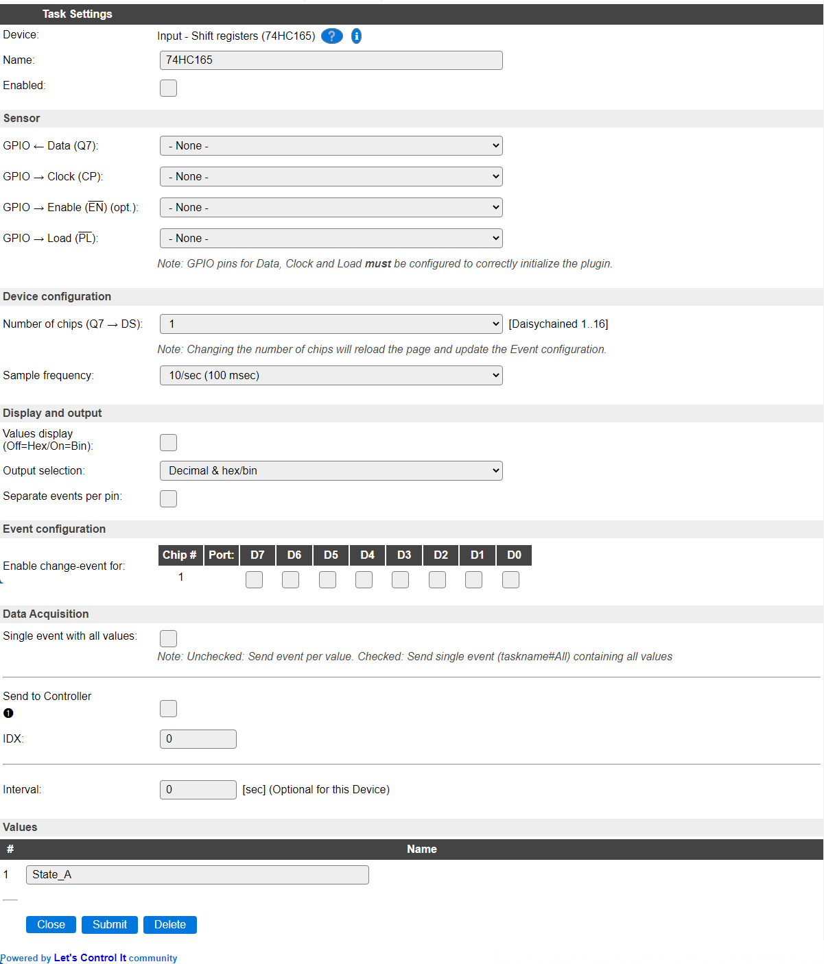
Name: A unique name should be entered here.
Enabled: The device can be disabled or enabled. When not enabled the device should not use any resources.
Actuator
GPIO -> Data (Q7): Select the GPIO pin that is connected to the Data out pin of the (first) shift register. Any daisy chained register has its
DSpin connected to theQ7pin of the previous shift register.GPIO -> Clock (CP): Select the Clock pin of all shift registers.
GPIO -> Enable (EN) (optional): Select the Enable pin of all shift registers, or set to None if not used or not available.
GPIO -> Load (PL): Select the Load pin of all shift registers.
NB: At least Data, Clock and Load GPIO pins need to be configured for the plugin to be able to function as intended.
Device configuration
Number of chips (Q7 -> DS): The number of chips daisy-chained to each other. Default: 1, max. 16 (compile-time defined, technically limited to 16), allowing for max. 128 input pins. When changing the number of chips, the page will be submitted and reloaded to update the Event configuration.
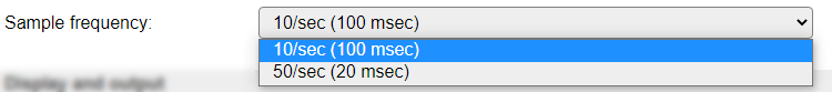
Sample frequency: The interval of reading the inputs from the shift registers, 10 times per second or 50 times per second.
Display and output
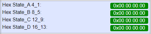
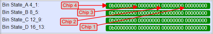
Values display (Off=Hex/On=Bin): The display on the Devices page is custom formatted to show the state of the inputs of the shift registers in either Hex (default) or Bin format, having a separator per chip (8 bits) for readability.
All zeroes, Hex display (default)
All zeroes, Bin display
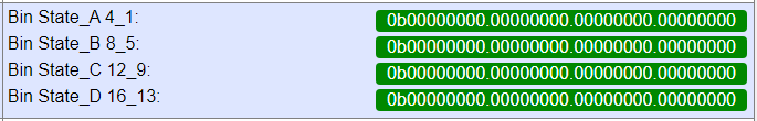
NB: The State values are grouped per 4 chips. To be read from right to left in chip-order, see below. If less chips are configured, only available states are shown.
Output selection: Choose the values that are sent out to any controllers configured, or when getting the value from processing
[<taskname>#<valuename>].
These are the available options:
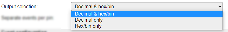
If Decimal & hex/bin is selected, the value is output twice, formatted as decimal and as hexadecimal (0x prefix) or binary (0b prefix), separated by a comma.
If either of the Hex/bin options is selected, but no Values display (Off=Hex/On=Bin) option is available, then the output will be formatted as hexadecimal.
Separate events per pin: When enabled, sends separate events per pin, including the pin number, to be processed via rules. F.e.
<TaskName>#<pin>=<state>,<chip>,<port>,<pin>. When disabled, all pins can be handled by a single rule, as it’s generated like:<TaskName>=<state>,<chip>,<port>,<pin>.
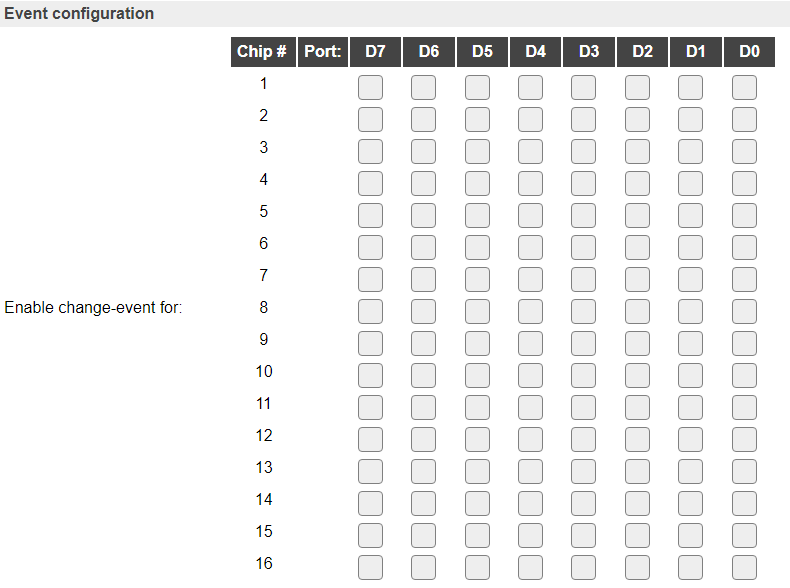
Event configuration
To select for which input an event should be generated, a matrix is shown, listing the pins per chip that can be separately enabled.
When all 16 chips are configured, the configuration looks like this:
Data Acquisition
This group of settings are standard available configuration items.
Single event with all values: When this setting is enabled, all available values will be sent in a single event
<TaskName>#All, with all values in order as arguments to the event.Show derived values: When checked, the Devices overview page, and the
/jsonendpoint (used for updating the Devices overview page) will include any Derived values as defined. See theTaskValueSetDerivedandTaskValueSetPresentationcommands.Event & Log derived values: When checked, the Derived values will be generated as Events, to be handled in Rules, and sent to logging devices like the Syslog server and/or SD-card logging.
(The derived values options are only available if String variables feature is included in the build.)
Send to Controller: Select the Controller(s) to send the Values to, either on a
TaskRuncommand applied to the task, or on an Interval time action.
Send to Controller is only visible when one or more Controllers are configured.
Depending on the controller capabilities, some configuration settings may be shown:

All configured Controllers are shown here, including the enabled or disabled state (multiple Controllers can be enabled, only a single MQTT Controller can be enabled at one time!).
For each controller the user can select wether the data should be sent on each Interval (or explicit TaskRun).
For the Domoticz controllers the value index (IDX) has to be configured.
For some controllers, like Home Assistant/openHAB, there are extra options available.
Group: This represents the group id to combine all values from multiple tasks into a single grouped-device during MQTT AutoDiscovery. Groups, by design, can span multiple ESPEasy devices, if desired, as long as the Task/Valuename combinations are unique. If a group should only combine Tasks from a single ESPEasy unit, the group id should be unique across multiple ESPEasy units. The group description, default Group <n>, can be adjusted in Home Assistant. If the Group value matches the current Unit nr, the Unit name,
%sysname%, is used instead of Group <nr>.Retained: For MQTT Controllers, this setting can be enabled to send the values for the current task with the Retain flag set. The Publish Retain flag in the Controller settings will override this by sending all task values with Retain flag enabled.
Send derived: This checkbox determines if any configured Derived values should also be sent to the controller (and included in the AutoDiscovery if that’s available and enabled).
Resend MQTT Discovery: When checked, will start a resend of the MQTT Discovery process for this task after a random delay, when Submit is clicked, so any changed settings will be updated in the MQTT broker. This setting is only available if the controller is enabled, the Auto Discovery feature is available and enabled for the controller. This setting is not stored.
Other controllers, like f.e. FHEM HTTP, do not support additional settings besides the checkbox to enable sending the data.
Interval By default, Interval will be set to 0 sec. as this is optional. Every Interval setting, the current output states will be read from the runtime object (not from the shift registers!) and stored in the Values fields, so they can be restored on a warm boot of the ESP.
Values
The Values State_A to State_D are used to show the state of up to 16 shift registers. (Custom formatted like set in Output selection.) Values that are not going to be filled are not shown here, and no events will be generated either.
Commands
The commands are all used to update configuration, not directly control the state of the shift registers.
Command Syntax |
Extra information |
|---|---|
ShiftIn,PinEvent,<pin>,<0|1> |
Enables or disables an event to be generated for the pin. Is updated in the configuration, but not saved.
|
ShiftIn,ChipEvent,<chip>,<0|1> |
Enables or disables an event to be generated for all pins of the selected chip. Is updated in the configuration, but not saved.
|
ShiftIn,SetChipCount,<count> |
Set the number of chips connected together. Is updated in the configuration, but not saved.
|
ShiftIn,SampleFrequency,<0|1> |
Select the sample frequency, 0 = 10/sec, 1 = 50/sec.
|
ShiftIn,EventPerPin,<0|1> |
Set or reset the
Separate event per pin option. Is updated in the configuration, but not saved. |
Events
Event |
Extra information |
|---|---|
<taskname>=<state>,<chip>,<port>,<pin>state: 0 or 1.chip: range 1..16, depending on the number of chips configured.port: range 1..8.pin: range 1..128, depending on the number of chips configured. |
Generic event for each activated input pin, that is enabled in the Event configuration matrix.
Generated if Separate events per pin is unchecked/disabled.
|
<taskname>#<pin>=<state>,<chip>,<port>,<pin>state: 0 or 1.chip: range 1..16, depending on the number of chips configured.port: range 1..8.pin: range 1..128, depending on the number of chips configured. |
Generic event for each activated input pin, that is enabled in the Event configuration matrix.
Generated if Separate events per pin is enabled.
|
<taskname>#<valuename>=[<decimalvalue>][,][<hex/binvalue>]Values provided depend on the setting Output selection.
|
The generic event per Value
State_A .. State_D, that are available, depending on the number of chips configured.Only sent if Interval is greater than 0, or an explicit
TaskRun command for this task is executed. |
Change log
Changed in version 2.0: added 2022-02-23 Added to ESPEasy as a new plugin.