Weight - HX711 Load Cell
.
Plugin details
Type: Weight
Name: HX711 Load Cell
Status ESP32: COLLECTION A
Status ESP8266: COLLECTION A
GitHub: P067_HX711_Load_Cell.ino
Maintainer: .
Used libraries: .
Supported hardware
.
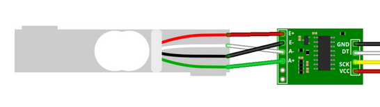
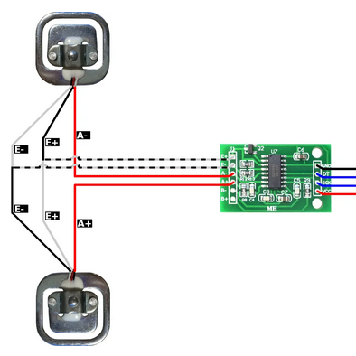
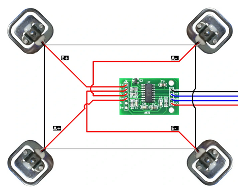
There are several ways to connect load cells to the HX711 board, depending on the number of load cells used.
1 load cell connected:
2 load cells connected:
4 load cells connected:
Separate A and B channels
When connecting 2 (sets of) load cells on both A and B channels, to get independent measurements, start with the 1, 2 or 4 load cell setup, above, then connect the E+ and E- wires of the second load cell (set) in parallel with the first load cell, the A- wire of the second load cell to B- input and the A+ wire to the B+ input of the board.
Description
The HX711 load-cell signal amplifier can be used for creating a scale, or to detect if the weight of an object changes. There can be 1, 2 or 4 load cells connected to each channel, in specific configurations as shown above.
Configuration
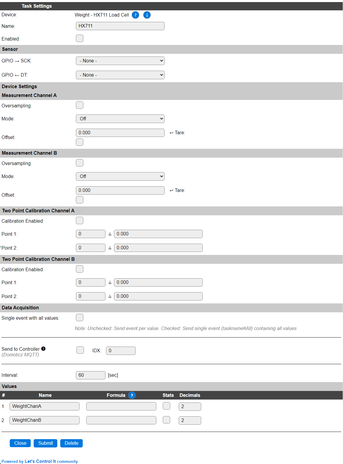
Name A unique name should be entered here.
Enabled The device can be disabled or enabled. When not enabled the device should not use any resources.
Sensor
GPIO -> SCK: The GPIO pin that is connected to the clock input of the board.
GPIO <- DT: The GPIO pin that is connected to the Data output of the board.
Device Settings
Measurement channel A
Oversampling: When enabled, the reported values are averaged during the set Interval to stabilize the, often somewhat fluctuating, returned values.
Mode: Channel A offers 3 modes of operation:
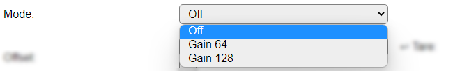
Off: The channel is disabled.
Gain 64: Enabled, signal enhancement with gain factor 64 is applied.
Gain 128: Enabled, signal enhancement with gain factor 128 is applied.
Offset: The offset is subtracted from the returned result. As each load cell has its own characteristic, this can be used to get a calibrated result value. The Tare checkbox (always off, unless checked by the user) can be used to fetch and set the last measured value as the offset.
Measurement channel B
The HX711 board offers a second input, often labelled B, where another load cell can be connected. To get the values of that channel, this part of the configuration has to be used.
Oversampling: When enabled, the reported values are averaged during the set Interval to stabilize the, often somewhat fluctuating, returned values. A new measurement sample is taken every 60 msec. (3 alternating measurements for the 3 gain options, 1 every 20 msec.) Max. 250 samples are used for oversampling.
Mode: Channel B offers 2 modes of operation:

Off: The channel is disabled.
Gain 32: Enabled, signal enhancement with gain factor 32 is applied.
Offset: The offset is subtracted from the returned result. As each load cell has its own characteristic, this can be used to get a calibrated result value. The Tare checkbox (always off, unless checked by the user) can be used to fetch and set the last measured value as the offset.
Note
The somewhat irregular Gain settings per channel as shown are a limitation in the HX711 hardware, not in the plugin or ESPEasy software.
Two Point Calibration Channel A
Calibration Enabled: Checked when 2-point calibration should be applied.
Point 1: The raw value, mapped to the desired output value.
Point 2: The raw value, mapped to the desired output value.
Two Point Calibration Channel B
Calibration Enabled: Checked when 2-point calibration should be applied.
Point 1: The raw value, mapped to the desired output value.
Point 2: The raw value, mapped to the desired output value.
Calibration procedure
To calibrate your measurements to a defined range, f.e. kg or g, this procedure can be used:
Make sure no load is on the load cell, the plugin is enabled, and some measurements have been registered (wait for the Interval time to have passed at least a few times, and non-zero values are shown in the device overview page).
Check the Calibration Enabled checkbox.
Reset the Point 1 and Point 2 values to 0 and 0.
Set the offset to the current measurement, by checking the Tare checkbox, and Submit the settings.
Place a reference-load of known value on the load cell that is near the highest range of measurement to be expected, f.e. 25 kg of weight on a 50 kg load cell if the regular measurement should be around 25 kg.
Take note of the measured value, either from the Devices overview page or the log, available via the serial interface or the Tools/Log page.
Set the Point 2 values to that measured value and the actual weight that was used, f.e. 25000 (g) or 25 (kg). When calibrating to
gthe value can still be shown inkgby applying the formula%value%/1000, optionally setting the number of decimals to 3 to show full resolution.Submit the page to store the calibration.
Note
Disclaimer: As the load versus output signal for a load cell isn’t guaranteed to be linear, calibration using the minimum and maximum expected load for calibration will result in a best effort output.
Data Acquisition
This group of settings are standard available configuration items.
Single event with all values: When this setting is enabled, all available values will be sent in a single event
<TaskName>#All, with all values in order as arguments to the event.Show derived values: When checked, the Devices overview page, and the
/jsonendpoint (used for updating the Devices overview page) will include any Derived values as defined. See theTaskValueSetDerivedandTaskValueSetPresentationcommands.Event & Log derived values: When checked, the Derived values will be generated as Events, to be handled in Rules, and sent to logging devices like the Syslog server and/or SD-card logging.
(The derived values options are only available if String variables feature is included in the build.)
Send to Controller: Select the Controller(s) to send the Values to, either on a
TaskRuncommand applied to the task, or on an Interval time action.
Send to Controller is only visible when one or more Controllers are configured.
Depending on the controller capabilities, some configuration settings may be shown:

All configured Controllers are shown here, including the enabled or disabled state (multiple Controllers can be enabled, only a single MQTT Controller can be enabled at one time!).
For each controller the user can select wether the data should be sent on each Interval (or explicit TaskRun).
For the Domoticz controllers the value index (IDX) has to be configured.
For some controllers, like Home Assistant/openHAB, there are extra options available.
Group: This represents the group id to combine all values from multiple tasks into a single grouped-device during MQTT AutoDiscovery. Groups, by design, can span multiple ESPEasy devices, if desired, as long as the Task/Valuename combinations are unique. If a group should only combine Tasks from a single ESPEasy unit, the group id should be unique across multiple ESPEasy units. The group description, default Group <n>, can be adjusted in Home Assistant. If the Group value matches the current Unit nr, the Unit name,
%sysname%, is used instead of Group <nr>.Retained: For MQTT Controllers, this setting can be enabled to send the values for the current task with the Retain flag set. The Publish Retain flag in the Controller settings will override this by sending all task values with Retain flag enabled.
Send derived: This checkbox determines if any configured Derived values should also be sent to the controller (and included in the AutoDiscovery if that’s available and enabled).
Resend MQTT Discovery: When checked, will start a resend of the MQTT Discovery process for this task after a random delay, when Submit is clicked, so any changed settings will be updated in the MQTT broker. This setting is only available if the controller is enabled, the Auto Discovery feature is available and enabled for the controller. This setting is not stored.
Other controllers, like f.e. FHEM HTTP, do not support additional settings besides the checkbox to enable sending the data.
Interval By default, Interval will be set to 60 sec. The minimum value allowed is 1 sec.
Note
The initial READ of the plugin, immediately after it is initializaed, will not return any data, as no measurement is read from the sensor yet. Only after the next Interval seconds a valid result is returned, as by then some data will have been collected.
Values
There are 2 values available for this sensor, named WeightChanA and WeightChanB. A formula can be set to recalculate, f.e. to apply a division, or multiplication, using %value%/1000. The number of decimals is by default set to 2.
Depending on the build-options used, a Stats checkbox per Value is available, and when checked, statistics for the value are stored in memory, and a graph can be shown in the Device configuration page. These statistics can be queried, similar like documented in the Analog Input - Internal plugin page.
Commands available
Command |
Extra information |
|---|---|
|
Use the last measured value for Channel A as the Offset/Tare value. NB: Use |
|
Use the last measured value for Channel B as the Offset/Tare value. NB: Use NB2: When setting the Tare for both A and B channel, use |
Change log
Changed in version 2.0: …
added 2023-01-01: Allow multiple instances of the plugin to be active, Channel B now returns a reliable result.
added Major overhaul for 2.0 release.
Added in version 1.0: …
added Initial release version.