Power mgt - AXP192 Power management ESP32
Power management controller
Plugin details
Type: Power mgt
Name: AXP192 Power management ESP32
Status ESP32: COLLECTION DISPLAY ENERGY NEOPIXEL
Status ESP8266: .
GitHub: P137_AXP192.ino
Maintainer: tonhuisman
Used libraries: https://github.com/tanakamasayuki/I2C_AXP192
Description
I2C Power management controller. As found in some ESP32 models of M5Stack and TTGO.
Plugin is only available in ESP32 builds, as the library uses some software constructs that aren’t available for ESP8266, and this controller is currently only found to be used with ESP32 boards.
Configuration
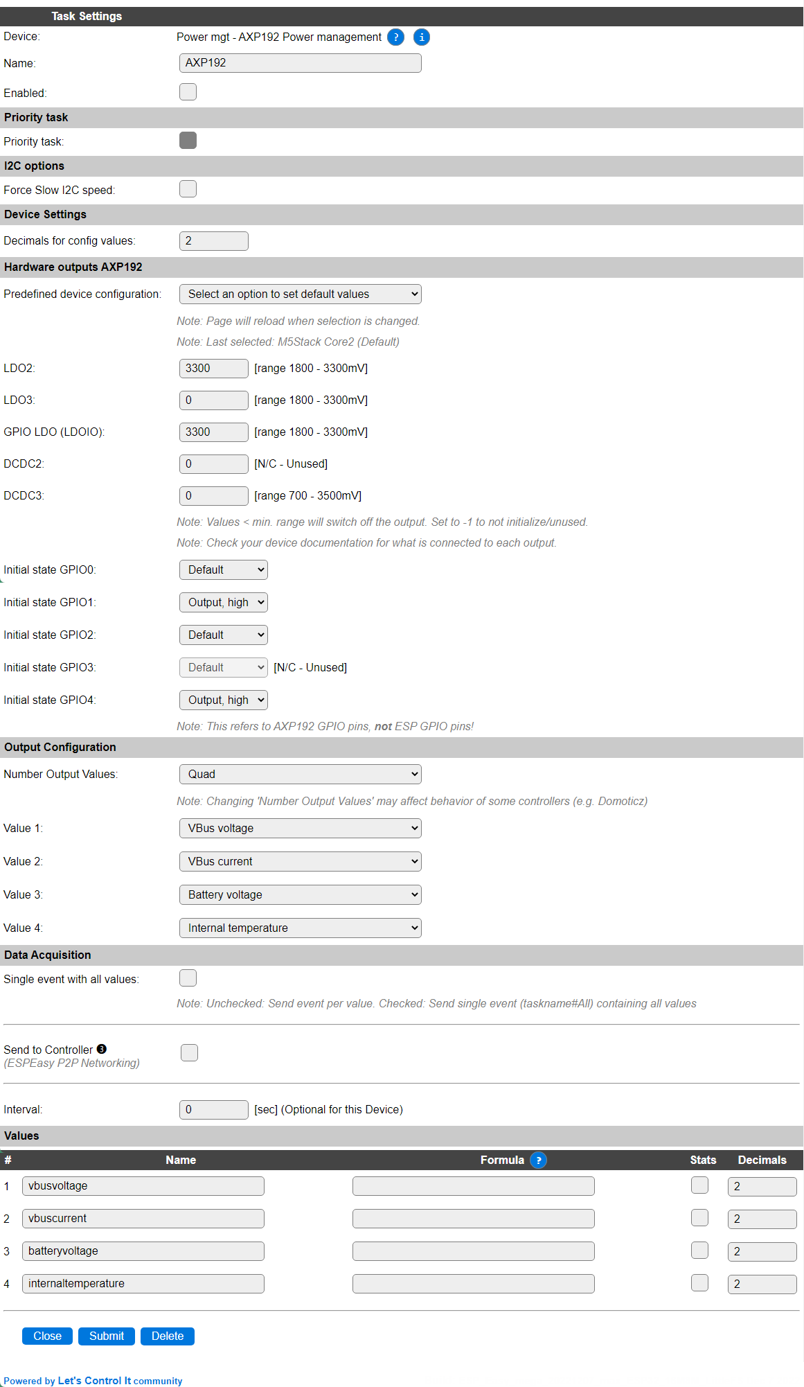
Name A unique name should be entered here.
Enabled The device can be disabled or enabled. When not enabled the device should not use any resources.
Priority task
Priority task: The Priority task option is available in selected plugins only, where they can be configured to be initialized as part of the ESPEasy hardware initialization procedure.
For some ESP devices, the installed controllers need to be powered on via a Power management device before they can be initialized, but as the Power management controllers are implemented as plugins, to use the available Device configuration infrastructure, a mechanism to load and initialize these plugins before parts of the hardware, like the SPI interface, are initialized, the Priority task option is available.
Enable a Priority task
Configure the plugin as desired and required: All settings must be completed before assigning the Priority task setting, as once enabled, no settings can be changed, to avoid the unit getting into a hardware deadlock.
Check if the settings are as intended: Just a double-check option to validate the plugin settings. This includes enabling the plugin.
Enable the Priority task option: Once the plugin is enabled, the settings are saved in that state, and no other Power management plugin is enabled as Priority task, the checkbox will be enabled, and can be checked.
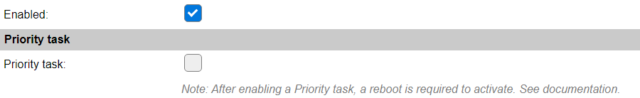
Save the plugin with enabled Priority task: Enable the checkbox, and Submit the device page. After the usual page reload, the Enabled checkbox, while it still looks available, can no longer be unchecked, the Predefined device configuration won’t reload the page, and the Submit and Delete buttons are no longer available.

Reboot the ESP: To complete the Priority task configuration, the device needs to be restarted. This can be achieved by a
rebootcommand, or using the Reboot button on the Tools page, a power cycle, or by pressing the reset button, if available.
When viewing the log during startup, these extra log messages are available at the Info level:
7982 : Info   : INIT : I2C
7985 : Info   : INIT : Check for Priority tasks
8035 : Info   : INIT : Started Priority task 1, [AXP192] Power mgt - AXP192 Power management
8036 : Info   : INIT : SPI not enabled
(The taskname and activated plugin can change, depending on the used Power mgt plugin.)
Note
An enabled Priority task can not be disabled, or re-enabled, using the TaskEnable,<task> and TaskDisable,<task> commands, to avoid hardware dead-lock situations.
Note
When a Priority task is enabled, on the Hardware tab the I2C GPIO configuration can not be changed anymore, as that could inhibit the correct working of the related plugin, and block the entire ESP unit from working as intended.
Now that the Power management controller is enabled and configured as a Priority task, the dependent hardware can be configured, in this case the SPI controller on the Hardware page.
After configuring the SPI settings, any Device that needs the SPI interface, like a TFT controller, can be configured as usual. Configuring the SPI settings may require to reset or power cycle the device.
Disable a Priority task
Prepare configuration to disable Priority task: If the Priority task needs to be disabled, it is required to execute a similar procedure as when enabling the Priority task, but in reverse order.
Disable Devices/Tasks that use the specific hardware: Any task that uses the hardware, controlled via the Priority task, like a TFT controller, must be disabled (and saved).
Disable the hardware interface: The same goes for the SPI interface, it must be disabled on the Hardware page, and the device should at least be rebooted, to activate that change.
Send the command to disable the priority task: To disable a priority task, a separate command is introduced:
disableprioritytask,<task>that takes 1 required argument, the name or number of a task that is a Priority task. This will disable the Priority task state in memory, but not save that state!Open the Device configuration: To complete disabling of the former Priority task, open the device confguration page for that task. You will notice that the Enabled checkbox is still disabled (can’t be clicked to change state). To complete this, the page should be saved using the Submit button. When the page is reloaded, also the task will be Disabled automatically! If so desired, instead of saving the page, the task can immediately be deleted by use of the Delete button.
Procedure completed: The Priority task is now disabled (or removed), and the settings are updated. After another reboot, the startup log will provide the matching information:
7882 : Info   : INIT : I2C
7886 : Info   : INIT : Check for Priority tasks
7896 : Info   : INIT : SPI not enabled
(No mention of a Priority task being started.)
[End of Priority task paragraph]
I2C Options
The available settings here depend on the build used. At least the Force Slow I2C speed option is available, but selections for the I2C Multiplexer can also be shown. For details see the I2C Bus page
Device Settings
Decimals for config values: The number of decimals to use for presenting the Config values (see below for a list of available values).
Hardware outputs AXP192
Predefined device configuration The plugin provides presets for some specific devices:
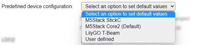
Select an option to set default values This option will always be selected when opening the page.
M5Stack StickC Settings for the M5Stack StickC hardware.
M5Stack Core2 (Default) Settings for the M5Stack Core and Core2, and derived special models, hardware. This is the default predefined configuration.
LilyGO T-Beam Settings for the LilyGO T-Beam series of GPS/LoRa devices with optional OLed display.
M5Stack StickC Plus Settings for the M5Stack StickC Plus hardware. (Not applicable for the M5Stack StickC Plus 2, as that unit doesn’t have an AXP192 power management controller).
User defined To be able to configure are available output pins the User defined option is available, f.e. when using a custom designed, or not yet supported, hardware setup.
When available, new predefined devices will be added. The User defined option will stay the last option.
The LDO2, LDO3, LDOIO, DCDC2 and DCDC3 outputs of the AXP192 can be set at a predefined value. When setting a value below 1800 mV, or 700 mV for the DCDC pins, the output will be turned off. Above 3300 mV is not supported/allowed, except for the DCDC3 pin that allows up to 3500 mV. Stepsize/resolution is ca. 100 mV.
Warning
Check board documentation for what each output is actually connected to, and the allowed voltage range for that output.
For the available GPIO pins (on AXP192, not ESP!), the initial state can be selected. The available options are:
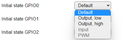
Default Doesn’t set the state of the GPIO pin.
Output, low Sets the state to low level (0 V).
Output, high Sets the state to high level.
Input Not supported yet.
PWM Not supported yet.
Output Configuration
Number Output Values: Select the number of values that have to be available. The default is set to Quad, as there are far more than 4 values available for display.
Available options: Single (1), Dual (2), Triple (3) and Quad (4).
Value 1..4: Select the desired value to be available in the Values fields. The name of the Values will be set to a matching default automatically, but can be changed afterward.
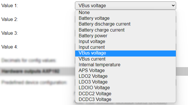
Available options:
None: To leave the value empty/0.00
Battery voltage: The voltage measured at the Battery connection.
Battery discharge current: The current that the battery is being discharged with.
Battery charge current: The current that the battery is being charged with.
Battery power: The power available from the battery.
Input voltage: The input voltage for the controller.
Input current: The input current used by the controller.
VBus voltage: The voltage at the VBus output.
VBus current: The current delivered via the VBus output.
Internal temperature: The internal chip temperature.
APS Voltage: The voltage at the APS output.
LDO2 voltage: The voltage at the LDO2 output.
LDO3 voltage: The voltage at the LDO3 output.
LDOIO voltage: The voltage at the GPIO (on AXP192, not ESP!) outputs.
DCDC2 voltage: The voltage at the DCDC2 output.
DCDC3 voltage: The voltage at the DCDC3 output.
Note
Not all options hold usable values for all boards, some may even be not connected. Check the board documentation for available values.
Data Acquisition
This group of settings are standard available configuration items.
Single event with all values: When this setting is enabled, all available values will be sent in a single event
<TaskName>#All, with all values in order as arguments to the event.Show derived values: When checked, the Devices overview page, and the
/jsonendpoint (used for updating the Devices overview page) will include any Derived values as defined. See theTaskValueSetDerivedandTaskValueSetPresentationcommands.Event & Log derived values: When checked, the Derived values will be generated as Events, to be handled in Rules, and sent to logging devices like the Syslog server and/or SD-card logging.
(The derived values options are only available if String variables feature is included in the build.)
Send to Controller: Select the Controller(s) to send the Values to, either on a
TaskRuncommand applied to the task, or on an Interval time action.
Send to Controller is only visible when one or more Controllers are configured.
Depending on the controller capabilities, some configuration settings may be shown:

All configured Controllers are shown here, including the enabled or disabled state (multiple Controllers can be enabled, only a single MQTT Controller can be enabled at one time!).
For each controller the user can select wether the data should be sent on each Interval (or explicit TaskRun).
For the Domoticz controllers the value index (IDX) has to be configured.
For some controllers, like Home Assistant/openHAB, there are extra options available.
Group: This represents the group id to combine all values from multiple tasks into a single grouped-device during MQTT AutoDiscovery. Groups, by design, can span multiple ESPEasy devices, if desired, as long as the Task/Valuename combinations are unique. If a group should only combine Tasks from a single ESPEasy unit, the group id should be unique across multiple ESPEasy units. The group description, default Group <n>, can be adjusted in Home Assistant. If the Group value matches the current Unit nr, the Unit name,
%sysname%, is used instead of Group <nr>.Retained: For MQTT Controllers, this setting can be enabled to send the values for the current task with the Retain flag set. The Publish Retain flag in the Controller settings will override this by sending all task values with Retain flag enabled.
Send derived: This checkbox determines if any configured Derived values should also be sent to the controller (and included in the AutoDiscovery if that’s available and enabled).
Resend MQTT Discovery: When checked, will start a resend of the MQTT Discovery process for this task after a random delay, when Submit is clicked, so any changed settings will be updated in the MQTT broker. This setting is only available if the controller is enabled, the Auto Discovery feature is available and enabled for the controller. This setting is not stored.
Other controllers, like f.e. FHEM HTTP, do not support additional settings besides the checkbox to enable sending the data.
Interval By default, Interval will be set to 0 sec. as it is optional. When set > 0 it is the frequency used to read sensor values and send these to any Controllers configured for this device.
Values
The measured values are available in variables, where the names are determined by the selected Value 1..4 settings. A formula can be set to recalculate. The number of decimals can be set as desired, and defaults to 2.
By enabling the Stats checkbox per Values entry, you enable the gathering of statistics, that can produce a nice graph of the collected values.
Commands
Command Syntax |
Extra information |
|---|---|
Commands to control the AXP192 output voltages and GPIO pins.
|
Attention: Commands will fail if the selected output is ‘N/C - Unused’ according to the selected Predefined device configuration.
|
axp,ldo2,<voltage>voltage range: 0..3300 mV. |
Set output
LDO2 to the specified voltage. When set below 1800 mV the output will be turned off. |
axp,ldo3,<voltage>voltage range: 0..3300 mV. |
Set output
LDO3 to the specified voltage. When set below 1800 mV the output will be turned off. |
axp,ldoio,<voltage>voltage range: 1800..3300 mV. |
Set AXP192 output for
LDOIO, setting the level for all GPIO pins of AXP192, to the specified voltage. When set below 1800 mV the command will fail. |
axp,ldo2perc,<percentage>percentage range: 1..100 %. |
Set output
LDO2 to the specified percentage within the mapping specified. The default mapping is the range from 1800..3300 mV, so 1% maps to 1800 mV and 100% to 3300mV. When set to 0 % the output will be turned off.See:
ldo2map sub-command below. |
axp,ldo3perc,<percentage>percentage range: 1..100 %. |
Set output
LDO3 to the specified percentage within the mapping specified. The default mapping is the range from 1800..3300 mV, so 1% maps to 1800 mV and 100% to 3300mV. When set to 0 % the output will be turned off.See:
ldo3map sub-command below. |
axp,ldoioperc,<percentage>percentage range: 1..100 %. |
Set AXP192
LDOIO outputs to the specified percentage within the mapping specified. The default mapping is the range from 1800..3300 mV, so 1% maps to 1800 mV and 100% to 3300mV. When set to 0 % the command will fail.See:
ldoiomap sub-command below. |
axp,dcdc2perc,<percentage>percentage range: 1..100 %. |
Set output
DCDC2 to the specified percentage within the mapping specified. The default mapping is the range from 700..2750 mV, so 1% maps to 700 mV and 100% to 2750mV. When set to 0 % the output will be turned off.See:
dcdc2map sub-command below. |
axp,dcdc3perc,<percentage>percentage range: 1..100 %. |
Set output
DCDC3 to the specified percentage within the mapping specified. The default mapping is the range from 700..3500 mV, so 1% maps to 700 mV and 100% to 3500mV. When set to 0 % the output will be turned off.See:
dcdc3map sub-command below. |
axp,ldo2map,<lowvoltage>,<highvoltage>lowvoltage, highvoltage range: 0..3300 mV.lowvoltage must be lower than highvoltage. |
Set the mapping range for
ldo2perc sub-command to the specified voltage range. |
axp,ldo3map,<lowvoltage>,<highvoltage>lowvoltage, highvoltage range: 0..3300 mV.lowvoltage must be lower than highvoltage. |
Set the mapping range for
ldo3perc sub-command to the specified voltage range. |
axp,ldoiomap,<lowvoltage>,<highvoltage>lowvoltage, highvoltage range: 1800..3300 mV.lowvoltage must be lower than highvoltage. |
Set the mapping range for
ldoioperc sub-command to the specified voltage range. |
axp,dcdc2map,<lowvoltage>,<highvoltage>lowvoltage, highvoltage range: 0..2750 mV.lowvoltage must be lower than highvoltage. |
Set the mapping range for
dcdc2perc sub-command to the specified voltage range. |
axp,dcdc3map,<lowvoltage>,<highvoltage>lowvoltage, highvoltage range: 0..3500 mV.lowvoltage must be lower than highvoltage. |
Set the mapping range for
dcdc3perc sub-command to the specified voltage range. |
axp,gpio0,<state>state: 0 (off/low) or 1 (on/high) |
Set the AXP192
GPIO0 pin state. |
axp,gpio1,<state>state: 0 (off/low) or 1 (on/high) |
Set the AXP192
GPIO1 pin state. |
axp,gpio2,<state>state: 0 (off/low) or 1 (on/high) |
Set the AXP192
GPIO2 pin state. |
axp,gpio3,<state>state: 0 (off/low) or 1 (on/high) |
Set the AXP192
GPIO3 pin state. |
axp,gpio4,<state>state: 0 (off/low) or 1 (on/high) |
Set the AXP192
GPIO4 pin state. |
Extra values
As this controller has more values available than can be set to the regular Values outputs, all values are also available from the Get Config feature.
|
The voltage measured at the Battery connection. |
|
The current that the battery is being discharged with. |
|
The current that the battery is being charged with. |
|
The power available from the battery. |
|
The input voltage for the controller. |
|
The input current used by the controller. |
|
The voltage at the VBus output. |
|
The current delivered via the VBus output. |
|
The internal chip temperature. |
|
The voltage at the |
|
The voltage at the |
|
The voltage at the |
|
The voltage at the (AXP192) |
|
The voltage at the |
|
The voltage at the |
Change log
Changed in version 2.0: added 2022-08-25 Initially added.