Motor - PWM Motor
.
Plugin details
Type: Motor
Name: PWM Motor
Status ESP32: COLLECTION A COLLECTION D
Status ESP8266: COLLECTION A COLLECTION D
GitHub: _P098_PWM_motor.ino
Maintainer: TD-er
Used libraries: .
Supported hardware
.
Configuration
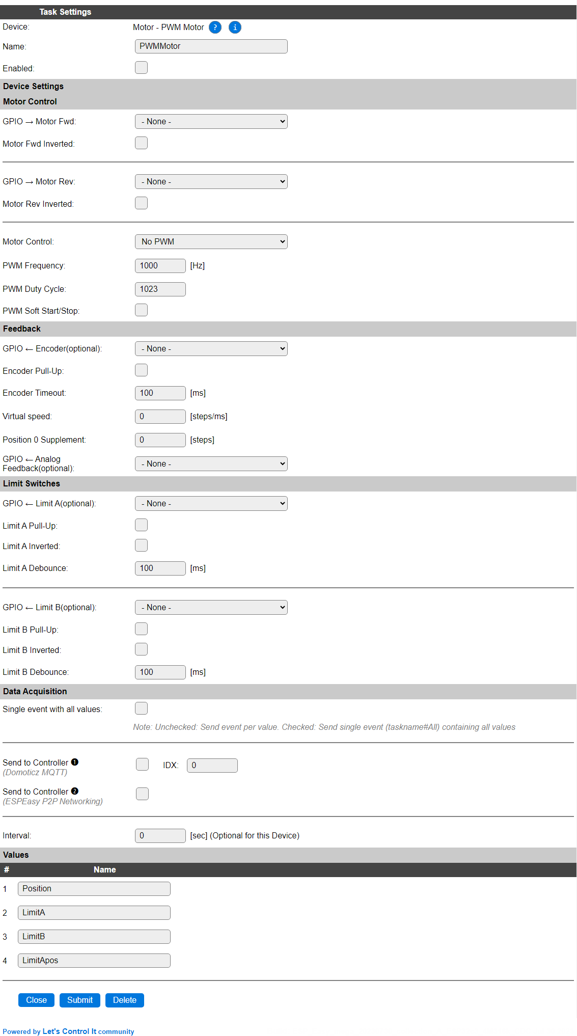
Name: Required by ESPEasy, must be unique among the list of available devices/tasks.
Enabled: The device can be disabled or enabled. When not enabled the device should not use any resources.
Motor Control
GPIO -> Motor Fwd: Select the GPIO that is connected to the Motor Forward connection.
Motor Fwd Inverted: Some motors need the signal to be inverted. This checkbox provides that option.
GPIO -> Motor Rev: Select the GPIO that is connected to the Motor Reverse connection.
Motor Fwd Inverted: Some motors need the signal to be inverted. This checkbox provides that option.
Motor Control: Select the type of motor control:
Available options:

No PWM: The motor is controlled by applying a High level (or Low when the matching Inverted option is checked) to the Forward or Reverse GPIO pin.
PWM: The motor is controlled by applying a PWM signal with the set frequency and duty-cycle (next options). Attention Check the documentation if the motor can be controlled via PWM, as in some cases this can cause damage to the motor or electronics involved!
PWM Frequency: The frequency of the PWM signal. Some motors run best at a specific frequency, usually noted in their documentation.
PWM Duty Cycle: The duty cycle of the PWM signal. Usually also specified in the motor documentation.
PWM Soft Start/Stop: This option will use a speed-fade-in at the start of moving, and fade-out near the end of moving. This makes the movement smoother.
Feedback
GPIO <- Encoder(optional): If the motor is equiped with a rotary encoder, the encoder signal can be connected to this GPIO pin. This is optional.
Encoder Pull-Up: When checked will activate the internal pull-up resistor for the Encoder GPIO. Depending on the encoder electronics a stronger (lower value like 4k7 or 10k) pull-up may be required, that should then be installed separately. This option can then be unchecked.
Encoder Timeout: The maximum time that is allowed for the encoder to start providing pulses after the motor movement is started.
Virtual speed: The number of steps/ms that the motor will move.
Position 0 Supplement: The number of steps that compensates for the overshoot or undershoot when moving to the Home position.
GPIO <- Analog Feedback(optional): Not implemented yet. Only available on ESP32.
Limit Switches
GPIO <- Limit A(optional): Select the GPIO that is connected to the Home-detection switch. This is optional.
Limit A Pull-Up: Enables the internal pull-up for the GPIO. When using longer wiring, a stronger (lower value like 4k7 or 10k) pull-up resistor may be required for a stable signal.
Limit A Inverted: Will invert the state of the limit switch.
Limit A Debounce: The limit-switch debounce time, range 0 to 1000 msec.
GPIO <- Limit B(optional): Select the GPIO that is connected to the End-detection switch. This is optional.
Limit B Pull-Up: Enables the internal pull-up for the GPIO. When using longer wiring, a stronger (lower value like 4k7 or 10k) pull-up resistor may be required for a stable signal.
Limit B Inverted: Will invert the state of the limit switch.
Limit B Debounce: The limit-switch debounce time, range 0 to 1000 msec.
Data Acquisition
This group of settings are standard available configuration items.
Single event with all values: When this setting is enabled, all available values will be sent in a single event
<TaskName>#All, with all values in order as arguments to the event.Show derived values: When checked, the Devices overview page, and the
/jsonendpoint (used for updating the Devices overview page) will include any Derived values as defined. See theTaskValueSetDerivedandTaskValueSetPresentationcommands.Event & Log derived values: When checked, the Derived values will be generated as Events, to be handled in Rules, and sent to logging devices like the Syslog server and/or SD-card logging.
(The derived values options are only available if String variables feature is included in the build.)
Send to Controller: Select the Controller(s) to send the Values to, either on a
TaskRuncommand applied to the task, or on an Interval time action.
Send to Controller is only visible when one or more Controllers are configured.
Depending on the controller capabilities, some configuration settings may be shown:

All configured Controllers are shown here, including the enabled or disabled state (multiple Controllers can be enabled, only a single MQTT Controller can be enabled at one time!).
For each controller the user can select wether the data should be sent on each Interval (or explicit TaskRun).
For the Domoticz controllers the value index (IDX) has to be configured.
For some controllers, like Home Assistant/openHAB, there are extra options available.
Group: This represents the group id to combine all values from multiple tasks into a single grouped-device during MQTT AutoDiscovery. Groups, by design, can span multiple ESPEasy devices, if desired, as long as the Task/Valuename combinations are unique. If a group should only combine Tasks from a single ESPEasy unit, the group id should be unique across multiple ESPEasy units. The group description, default Group <n>, can be adjusted in Home Assistant. If the Group value matches the current Unit nr, the Unit name,
%sysname%, is used instead of Group <nr>.Retained: For MQTT Controllers, this setting can be enabled to send the values for the current task with the Retain flag set. The Publish Retain flag in the Controller settings will override this by sending all task values with Retain flag enabled.
Send derived: This checkbox determines if any configured Derived values should also be sent to the controller (and included in the AutoDiscovery if that’s available and enabled).
Resend MQTT Discovery: When checked, will start a resend of the MQTT Discovery process for this task after a random delay, when Submit is clicked, so any changed settings will be updated in the MQTT broker. This setting is only available if the controller is enabled, the Auto Discovery feature is available and enabled for the controller. This setting is not stored.
Other controllers, like f.e. FHEM HTTP, do not support additional settings besides the checkbox to enable sending the data.
Interval: Interval is optional, and will be set to 0 sec. The data will be collected and optionally sent to any configured controllers using this interval.
Values
The plugin provides the Position, LimitA, LimitB and LimitApos values. LimitA or LimitB will be set to 1 when the motor is at that position, and the matching settings are configured, above.
Commands available
Command |
Extra information |
|---|---|
Move the motor to the Home position. |
Revert the motor until the limit switch A, aka Home, position is reached. This will cause the |
Move the motor to the End position. |
Move the motor forward until the limit switch B, aka End, position is reached. This will cause the |
Move the motor forward.
|
Move the motor a number of steps, or until the limit switch B, aka End, position is reached. If This will cause the |
Move the motor backward (reverse).
|
Move the motor a number of steps, or until the limit switch A, aka Home, position is reached. If This will cause the |
Stop the motor. |
Stop the motor moving (if, of course, it is moving). |
Move the motor to an absolute position. |
Move the motor to an absolute position. Expects to have the Home position defined, by moving to the Home position at least once. This will cause the |
Events
Event |
Example |
|---|---|
Limit switch A is reached |
If limit switch A is configured, then this event will be generated once the switch is reached. |
Limit switch B is reached |
If limit switch B is configured, then this event will be generated once the switch is reached. |
Requested position is reached |
After a command |
A time-out has occurred. |
The command took longer then the configured time-out duration, causing this event to be generated. |
Change log
Added in version 2.0: …
added Initial release version.