Analog input - PCF8591
.
Plugin details
Type: Analog input
Name: PCF8591
Status ESP32: NORMAL
Status ESP8266: NORMAL
GitHub: P007_PCF8591.ino
Maintainer: .
Used libraries: .
Introduction
The PCF8591 is an Analog to Digital and Digital to Analog converter, connected via an I2C bus. The plugin supports to read from 1 up to 4 input values, and has a single analog output that can be changed by a command. If desired, multiple Tasks can be defined, addressing other, or duplicate, inputs.
Supported hardware
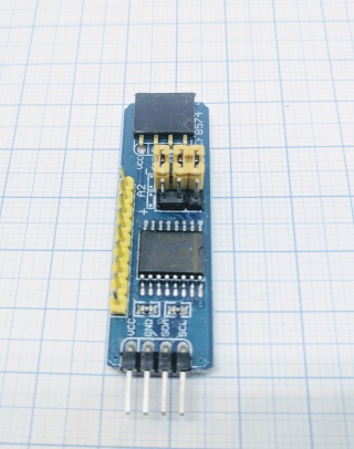
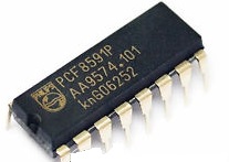
The chip is separately available, or on a complete module, and can be bought from several sources.
it is compatible with 3.3V logic, when powered with 3.3V, so no level converters are needed to connect it to an ESP.
.
Configuration
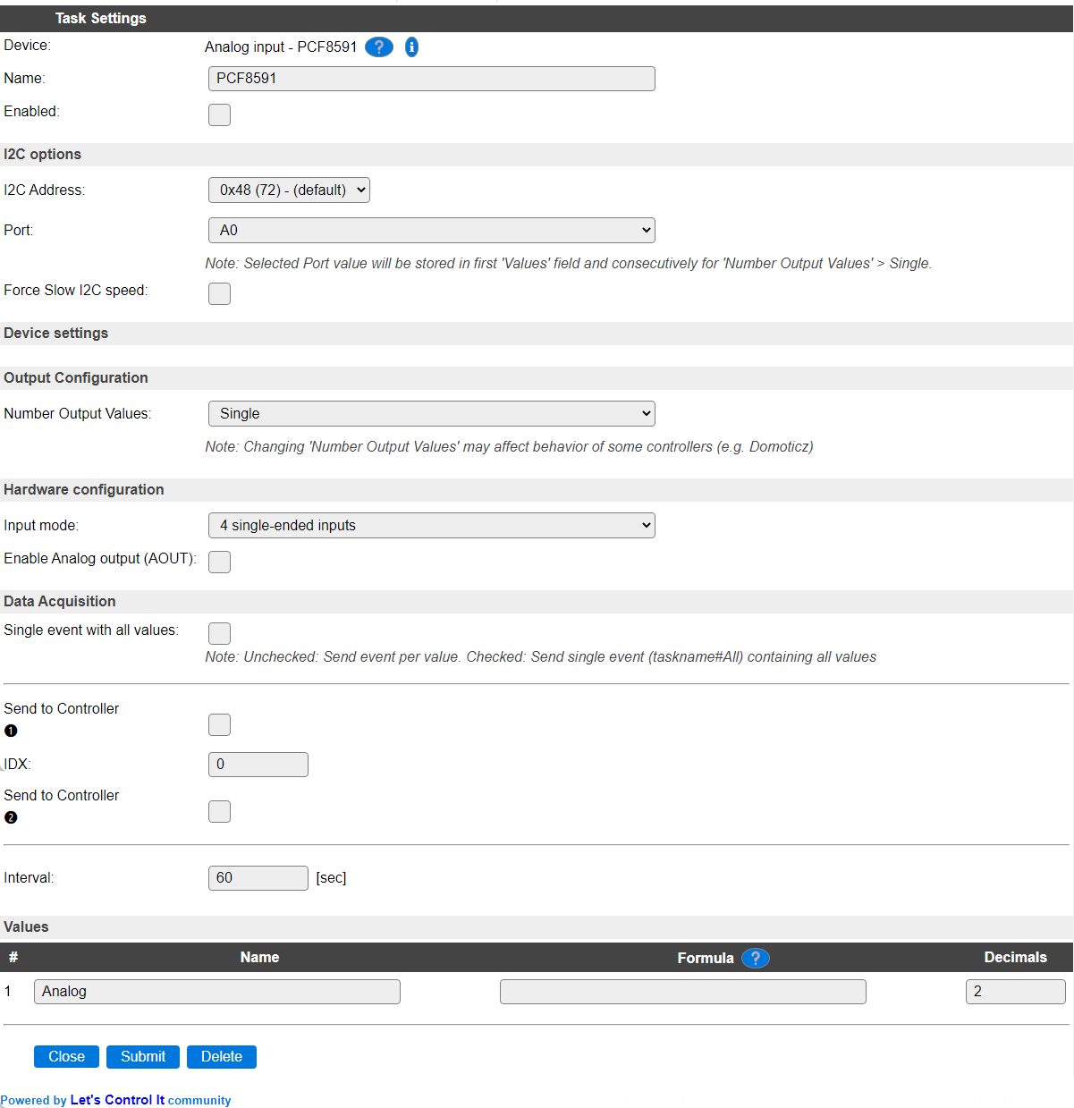
Name A unique name should be entered here.
Enabled The device can be disabled or enabled. When not enabled the device should not use any resources.
I2C Options
The available settings here depend on the build used. At least the Force Slow I2C speed option is available, but selections for the I2C Multiplexer can also be shown. For details see the I2C Bus
As the chip is specified to only work correctly up to 100 kHz, the Force Slow I2C speed checkbox should normally be enabled.
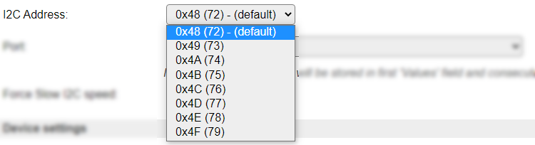
I2C Address: The address the device is using. There are a number of addresses the module can use, and they can usually be set at the board using jumper pins.
The available options:
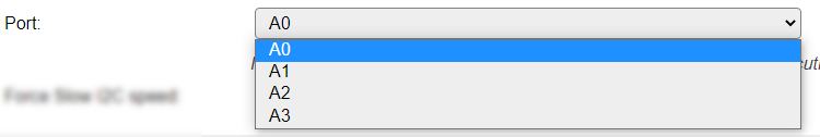
Port As there are multiple Ports available on each board, the desired Port can be selected here.
Available options:
Force Slow I2C Speed Should be enabled, as by PCF8591 chip specification, the I2C bus clock should be max. 100 kHz. This is the default Slow device Clock Speed I2C setting for ESPEasy (see Hardware tab). When using the default I2C Clock Speed of 400 kHz, readings will be unreliable, especially when reading multiple values in 1 task.
Output Configuration
Number Output Values As this device supports 4 Analog inputs, the number of measurements handled by this task can be configured.
Available options:
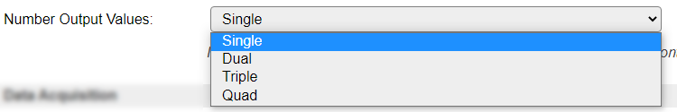
The names should speak for themselves.
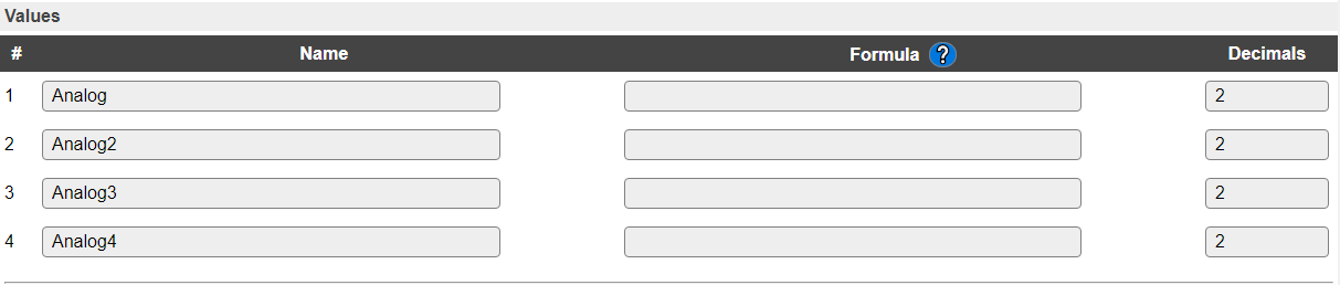
When selecting f.e. the Quad option and saving the settings, the number of output values is changed to 4, resulting in these Values:
Note
If Port is set to A1, A2 or A3, then the value measured from the selected Port will be stored in the first Values field, and any next field(s) consecutively. If Number Output Values is larger than the remaining number of Ports, then the remaining Values will be set to 0!
For any ‘excess’ values, events will be generated!
Hardware configuration
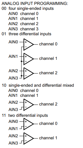
Input mode The chip supports several input modes, the desired mode can be selected here.
Available options are:
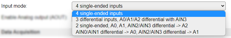
4 single-ended inputs De standard configuration is to have 4 inputs that are measured with regards to GND.
3 differential inputs, A0/A1/A2 differential with AIN3 AIN0 .. AIN2 are measured differential to AIN3, resulting in 3 available values.
2 single-ended, A0, A1, AIN2/AIN3 differential -> A2 AIN0 and AIN1 are measured with regards to GND into the first 2 values, the third value is measured differentially from AIN2 and AIN3.
AIN0/AIN1 differential -> A0, AIN2/AIN3 differential -> A1 2 values are measured, the first differentially from AIN0 and AIN1, and the second differentially from AIN2 and AIN3.
When configuring a differential option from above list, the 4th and 3rd values are undefined when not used, but can still be read. The results are then undefined.
The chip documentation describes it like this:
Enable Analog output (AOUT) Enabling the Analog output has 2 effects:
The AOUT pin can be set to a linear value in the range 0..255 between 0V and Vref (Vref can sometimes be set using a potentiometer on the board) using the
analogoutcommand (see below).The internal oscillator will be enabled continuesly, causing higher power usage, but also improved measurements when reading an analog input as it avoids the startup time of the oscillator that can cause inaccurate readings.
Data Acquisition
This group of settings are standard available configuration items.
Single event with all values: When this setting is enabled, all available values will be sent in a single event
<TaskName>#All, with all values in order as arguments to the event.Show derived values: When checked, the Devices overview page, and the
/jsonendpoint (used for updating the Devices overview page) will include any Derived values as defined. See theTaskValueSetDerivedandTaskValueSetPresentationcommands.Event & Log derived values: When checked, the Derived values will be generated as Events, to be handled in Rules, and sent to logging devices like the Syslog server and/or SD-card logging.
(The derived values options are only available if String variables feature is included in the build.)
Send to Controller: Select the Controller(s) to send the Values to, either on a
TaskRuncommand applied to the task, or on an Interval time action.
Send to Controller is only visible when one or more Controllers are configured.
Depending on the controller capabilities, some configuration settings may be shown:

All configured Controllers are shown here, including the enabled or disabled state (multiple Controllers can be enabled, only a single MQTT Controller can be enabled at one time!).
For each controller the user can select wether the data should be sent on each Interval (or explicit TaskRun).
For the Domoticz controllers the value index (IDX) has to be configured.
For some controllers, like Home Assistant/openHAB, there are extra options available.
Group: This represents the group id to combine all values from multiple tasks into a single grouped-device during MQTT AutoDiscovery. Groups, by design, can span multiple ESPEasy devices, if desired, as long as the Task/Valuename combinations are unique. If a group should only combine Tasks from a single ESPEasy unit, the group id should be unique across multiple ESPEasy units. The group description, default Group <n>, can be adjusted in Home Assistant. If the Group value matches the current Unit nr, the Unit name,
%sysname%, is used instead of Group <nr>.Retained: For MQTT Controllers, this setting can be enabled to send the values for the current task with the Retain flag set. The Publish Retain flag in the Controller settings will override this by sending all task values with Retain flag enabled.
Send derived: This checkbox determines if any configured Derived values should also be sent to the controller (and included in the AutoDiscovery if that’s available and enabled).
Resend MQTT Discovery: When checked, will start a resend of the MQTT Discovery process for this task after a random delay, when Submit is clicked, so any changed settings will be updated in the MQTT broker. This setting is only available if the controller is enabled, the Auto Discovery feature is available and enabled for the controller. This setting is not stored.
Other controllers, like f.e. FHEM HTTP, do not support additional settings besides the checkbox to enable sending the data.
Interval By default, Interval will be set to 60 sec. It is the frequency used to read sensor values and send these to any Controllers configured for this device.
Values
The name for the value(s) is initially set to a default name, but can be changed if desired. Also, a formula can be entered to re-calculate a value before display/sending to a controller, and the number of decimals can be changed, for a Temperature, usually 1 decimal is enough to be displayed (value will be rounded).
Commands available
Command |
Extra information |
|---|---|
Value: 0..255 |
The value is linearly scaled from 0V to Vref. Vref is often the same as VCC for the chip, but can sometimes be configured using a potentiometer on the board. Only available if Enable Analog output (AOUT) is enabled. |
Change log
Changed in version 2.0: …
added
2022-05-08 Selection of Input mode, Enable Analog output (AOUT) and analogout command.
added 2021-08-06 Selection of 1 to 4 input values to be read.
changed 2021-08-03 Replaced single Port inputfield with separate I2CAddress and Port selections.
added Major overhaul for 2.0 release.
Added in version 1.0: …
added Initial release version.