Output - Shift registers (74HC595)
Output shift registers
Plugin details
Type: Output
Name: Shift registers (74HC595)
Status ESP32: COLLECTION E
Status ESP8266: COLLECTION E
GitHub: P126_74HC595.ino
Maintainer: tonhuisman
Used libraries: https://timodenk.com/blog/shift-register-arduino-library/ (Un-Templated, modified local copy)
Description
The 74HC595 Shift registers can be used to connect many output pins to an ESP using only 3 GPIO pins, as these shift registers can easily be daisy chained. There are several shift registers compatible with the 74HC595, like the 74HC164 or TPIC6B595, and probably a couple more.
When connecting many shift registers daisy-chained, it is important to ensure that not too many are connected to a single GPIO output pin, as that could overload that pin. It is advised to use a buffer chip for all used GPIOs for every 4 to 5 shift registers. When using a Schmitt-trigger buffer, it will also clean up the signal further down the line. Any buffer will introduce a small delay in the signal, possibly reducing the number of shift registers that can be controlled. A few useful answers are in this Stack Exchange question
The output pins can be used to control f.e. relays or LEDs. NB: When using 74HC164, be aware that these don’t use an output latch buffer, meaning the outputs are activated immediately according to the bits sent, so these are less applicable for relays. The logic is built so that on crash or reboot of the ESP, the last used state can be restored from RTC memory (enabled by default), so the state of the outputs is kept. This is limited to max. 16 shift registers, as that is the size of the memory reserved per task in RTC memory. This memory only survives a warm boot, not a reset or power-cycle!
The register outputs are not updated during initialization of the plugin; only when changing a pin state, or using the ShiftOut,Update command, the shift register outputs are updated.
Configuration
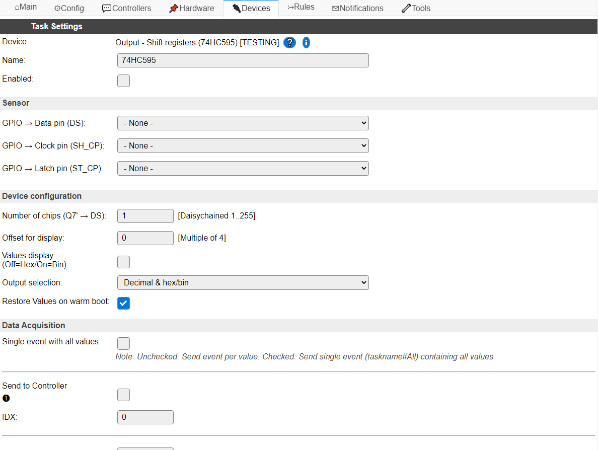
Name A unique name should be entered here.
Enabled The device can be disabled or enabled. When not enabled the device should not use any resources.
Sensor
GPIO -> Data pin (DS): Select the GPIO pin that is connected to the Data in pin
DSof the (first) shift register. Any daisy chained register has itsDSpin connected to theQ7'pin of the previous shift register.GPIO -> Clock pin (SH_CP): Select the Clock pin of all shift registers.
GPIO -> Latch pin (ST_CP): Select the Latch pin of all shift registers.
Device configuration
Number of chips (Q7’ -> DS): The number of chips daisy-chained to each other. Default: 1, max. 255 (compile-time defined, technically limited to 255), allowing for max. 2040 output pins.
Offset for display: This setting determines which set of chip states are displayed on the Devices screen, but, more importantly, which will be restored from RTC memory on a warm boot of the ESP.
ESPEasy stores the current values of each task in RTC memory (that is retained during a warm boot, not a reset or power cycle), and restores their values if possible. This plugin uses the setting Restore Values on warm boot to determine if these values should then be used as the new state for the shift registers, allowing the outputs to survive a warm boot of the ESP.
Using Offset for display, the chips that will be restored, with a maximum of 16, are configured. This value is always rounded to a multiple of 4, and lower than the number of chips configured.
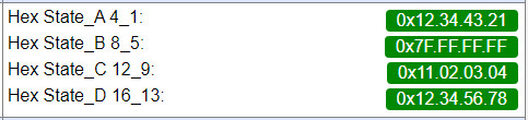
Values display (Off=Hex/On=Bin): The display on the Devices page is custom formatted to show the state of the outputs of the shift registers in either Hex (default) or Bin format, having a separator per chip (8 bits) for readability.
Some random values, Hex display (default)
Some random values, Bin display (16 chips visible)
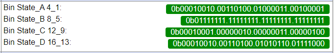
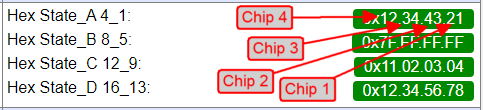
NB: The State values are grouped per 4 chips. To be read from right to left in chip-order, see image below. If less chips are configured, only available states are shown. Display is started at the Offset for display + 1 chip.
Output selection: Choose the values that are sent out to any controllers configured, or when getting the value from processing
[<taskname>#<valuename>].
These are the available options:
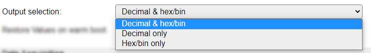
If Decimal & hex/bin is selected, the value is output twice, formatted as decimal and as hexadecimal or binary, separated by a comma.
If either of the Hex/bin options is selected, but no Values display (Off=Hex/On=Bin) option is available, then the output will be formatted as hexadecimal.
Restore Values on warm boot: By default, the register states are restored from RTC memory, so the outputs are in their previous state after a warm boot of the ESP. When turned off, all outputs will be turned off (low) on the next update.
Data Acquisition
This group of settings are standard available configuration items.
Single event with all values: When this setting is enabled, all available values will be sent in a single event
<TaskName>#All, with all values in order as arguments to the event.Show derived values: When checked, the Devices overview page, and the
/jsonendpoint (used for updating the Devices overview page) will include any Derived values as defined. See theTaskValueSetDerivedandTaskValueSetPresentationcommands.Event & Log derived values: When checked, the Derived values will be generated as Events, to be handled in Rules, and sent to logging devices like the Syslog server and/or SD-card logging.
(The derived values options are only available if String variables feature is included in the build.)
Send to Controller: Select the Controller(s) to send the Values to, either on a
TaskRuncommand applied to the task, or on an Interval time action.
Send to Controller is only visible when one or more Controllers are configured.
Depending on the controller capabilities, some configuration settings may be shown:

All configured Controllers are shown here, including the enabled or disabled state (multiple Controllers can be enabled, only a single MQTT Controller can be enabled at one time!).
For each controller the user can select wether the data should be sent on each Interval (or explicit TaskRun).
For the Domoticz controllers the value index (IDX) has to be configured.
For some controllers, like Home Assistant/openHAB, there are extra options available.
Group: This represents the group id to combine all values from multiple tasks into a single grouped-device during MQTT AutoDiscovery. Groups, by design, can span multiple ESPEasy devices, if desired, as long as the Task/Valuename combinations are unique. If a group should only combine Tasks from a single ESPEasy unit, the group id should be unique across multiple ESPEasy units. The group description, default Group <n>, can be adjusted in Home Assistant. If the Group value matches the current Unit nr, the Unit name,
%sysname%, is used instead of Group <nr>.Retained: For MQTT Controllers, this setting can be enabled to send the values for the current task with the Retain flag set. The Publish Retain flag in the Controller settings will override this by sending all task values with Retain flag enabled.
Send derived: This checkbox determines if any configured Derived values should also be sent to the controller (and included in the AutoDiscovery if that’s available and enabled).
Resend MQTT Discovery: When checked, will start a resend of the MQTT Discovery process for this task after a random delay, when Submit is clicked, so any changed settings will be updated in the MQTT broker. This setting is only available if the controller is enabled, the Auto Discovery feature is available and enabled for the controller. This setting is not stored.
Other controllers, like f.e. FHEM HTTP, do not support additional settings besides the checkbox to enable sending the data.
Interval: By default, Interval will be set to 0 sec. as this is optional for this plugin. Every Interval setting, the current output states will be read from the runtime object (not from the shift registers!) and stored in the Values fields, so they can be restored on a warm boot of the ESP.
Values
The Values State_A to State_D are used to store the state of up to 16 shift registers to survive a warm boot.
Commands
Command Syntax |
Extra information |
|---|---|
ShiftOut,Set,<pin>,<0|1> |
Set
<pin> to the state provided. Pin numbers start at 1 and continue up to no. of chips * 8. The shift registers are updated immediately |
ShiftOut,SetNoUpdate,<pin>,<0|1> |
Set
<pin> to the state provided. Pin numbers start at 1 and continue up to no. of chips * 8. The shift registers are not updated. See ShiftOut,Update command. |
ShiftOut,Update |
Update the current buffered state to the shift registers.
|
ShiftOut,SetAll,[chip:][width:]<value>... |
Set the addressed chip(s) with the value provided. Values should be max. 32 bit. Chip starts at 1 by default, and width is 4 by default. Shift registers are updated immediately.
To select a single chip with 8 bits of data, use a
width of 1, use 2 for updating 2 adjacent chips with a 16 bit value, etc. |
ShiftOut,SetAllNoUpdate,[chip:][width:]<value>... |
See
ShiftOut,SetAll command, but without immediate update to the shift registers. See ShiftOut,Update command to set the output to the shift registers. |
ShiftOut,SetAllLow |
Switch all shift register outputs to off (low). Immediately updates the shift registers.
|
ShiftOut,SetAllHigh |
Switch all shift register outputs to on (high). Immediately updates the shift registers.
|
ShiftOut,SetChipCount,<chip count> |
Change the number of chips configured. Will adjust the configuration immediately, and set in Device configuration, but not store the setting, use the
save command for storing the setting.When increasing the number of chips, the extra outputs will all be set to low/off.
|
ShiftOut,SetOffset,<chip offset> |
Change the
Offset for display configuration setting. Does not save the setting, use the save command for storing the setting. |
ShiftOut,SetHexBin,<0|1> |
Change the Values display (Off=hex/On=Bin) setting to on (1) or off (0). Does not save the setting, use the
save command for storing the setting. |
Change log
Changed in version 2.0: added 2022-01-28 Added to ESPEasy as a new plugin.