Regulator - Level Control
.
Plugin details
Type: Regulator
Name: Level Control
Status ESP32: NORMAL CLIMATE
Status ESP8266: NORMAL CLIMATE
GitHub: P021_Level.ino
Maintainer: .
Used libraries: .
Introduction
It is always helpful to have some sort of local level control. This is something that would normally be handled by a Home Automation controller, but if you really need to have something like a locally controlled heater, you could use the Level Control plugin.
The ESP module can be used as a level controlling device, think of a simple temperature control unit. Use a DS18B20, BME280 or similar temperature sensor and a mechanical or solid state relay to control a heater. Connect this relay to a GPIO pin.
The control algorithm can be a simple value to setpoint comparator with hysteresis to prevent the relay switching too often in a short period. Pumps like used for floor heating have some additional requirements like running once in a while and keeping the pump running for a minimum time. The plugin provides a simple “Classic” mode of operation which can be extended with additional features.
Note: Due to size limitations some builds contain limited functionality. State control extension and remote control will not be available on these standard builds for ESPeasy. You can always create a custom build with full functionality.
Basic control algorithm
The output of another plugin is used as measurement input. This input is compared with a given Setpoint. If the Input is above the Setpoint the Output (heater/pump) should be switched on (becomes active); If it is below the setpoint the Output should be switched off (becomes inactive). If the Input is close to the Setpoint the controller might switch very rapidly between on and off (flip-flopping). This may destroy the relay or pump. A margin between switch on and switch off level is used to prevent this flip-flopping. When the Input value stays between these two levels the output will not be changed. This margin is called Hysteresis. The Hysteresis can be symetrical around the Setpoint: Switching on above (Setpoint + 0.5*Hysteresis) and switching off below (Setpoint - 0.5*Hystersis). With an asymetrical Hysteresis the output is switched on above the Setpoint and switched of below (Setpoint - Hysteresis).
In case of symetrical hysteresis there is an exception in hysteresis handling: If the Hysteresis is set to 0, the output state will become active if the measured value goes below Setpoint, and the output state will become inactive if the measured value reaches Setpoint + 1.0.
It is strongly advised to use a proper non-zero Hysteresis tuned to the behavior of the control process and not to rely on this exception.
To facilitate various applications the direction of the input comparator can be inverted. Combining symetrical hystersis and invert output this results in the following overview:

State control extension
To provide additional control features the controller can be in one of several States. Based upon the input value and some timers the controller can change the State. The output of the controller directly depends on the State. The following states exist:
Idle : The Output is swiched to inactive (off). There is no reason to switch it active (on).
Active : The basic comparator algorithm decides the Output must be switched to active. There is a demand based upon the measured Input value.
Extend : The Output was switched on for a too short period. It will be kept running for a minimum time even while the comparator algorithm has no demand.
Force : The output is forced on for a minimum amount of time to keep the system in condition. The State will be set to Forced when the Output is inactive for a too long time.
Extension of the period the Output is kept active depends on the use case. Extension from the moment of activating the Output is used to prevent a heater or pump is running too short cycles. Extension when the demand drops (input below setpoint) is used optimize the control process. For example a heating pump is kept running for some time to spread the remaining heat.
Remote control
It may be useful to manipulate the local controller from a Home Automation controller. The plugin accepts commands to change the following settings:
Setpoint : This command changes the actual Setpoint for the local control algorithm.
Hysteresis : This command changes the actual Hysteresis for the local control algorithm.
Remote : This command can override the basic control algorithm. It can be used to force the Output to on. Usecase is a floor heating pump that should be switched on as soon as the central heating system is swiched on.
Operation modes
The controller can be set to one of the following operation modes:
CLASSIC : Basic control algorithm without state control extension. This mode is backwards compatible with earlier versions of this plugin.
OFF : The output is always switched off.
STANDBY : The output is off with the maintenance check active. The output is switched on after maximum idle time.
ON : The output is always switched on.
LOCAL : Control algorithm with state control extension. Only local control input is used.
REMOTE : Control algorithm with state control extension. Both local control and remote command input is used.
Backwards compatibility
This plugin is extended with new state control features. New settings are added such that existing users should not need to modify their settings when upgrading to a newer ESPeasy version. As a result some of the added settings may seem a bit strange as they must default to the original behavior. To achieve this behavior CLASSIC control mode with symetrical Hysteresis is selected as default.
Configuration
Configuration settings in classic mode:

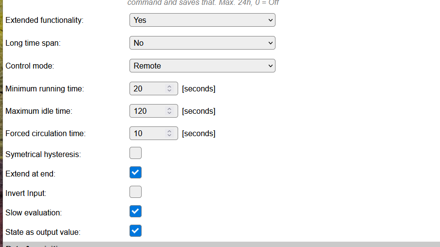
In extended mode additional settings are available:
Name A unique name should be entered here.
Enabled The device can be disabled or enabled. When not enabled the device should not use any resources.
Sensor
GPIO -> Output Select a GPIO pin that will be updated when the Output state changes. The state is applied directly on the GPIO pin, so only On (1) and Off (0) will be set.
Input Task Select the Task that should be monitored. Initially the first Task will be selected. Only configured tasks can be selected.
Input Value After selecting the task, the value that should be monitored can be selected. Initially, the first value of the task is selected.
Setpoint The value that is to be maintained. Decimals can be used in this value.
Hysteresis To avoid ‘flip-flopping’ of the output, some hysteresis should be applied to the Setpoint. The value entered here will be applied as described above in Basic control algorithm.
Invert Output When checked, the output state will be 0 instead of 1 when the level is activated.
Save ‘Set Level’ after change via config command Via the config command, the Set Level value can be changed. To avoid wearing out the flash memory of the device by too often saving these settings, the default is now off, for existing tasks (after upgrade of ESPEasy), the old behavior of saving after each change is still active. The user should decide if saving the setting is actually required, or if that can be attained by carefully planning a save command or via a manual save.
Auto-save interval Here a time in minutes can be set after which any changed ‘Set Level’ via the
config,task,<taskname>,SetLevel,<value>command will be saved. This requires that the above setting Save ‘Set Level’ after change via config command is disabled! When used, a setting of ca. 30 minutes, or even longer when the Set Level is changed often, seems apropriate, unless the unit often reboots, but then that cause should be investigated and solved. The timer, when activated, should survive a warm reboot.
Warning
Saving settings too often will cause damage to the Flash memory of the unit!
Extended functionality1) Enable new functionality. Changing this will reload the form showing/hiding the new options below.
Long time span1) Timer values are per default entered in [seconds], enabling this option timing settings are tuned to long intervals using [hours] or [seconds]. Changing this will reload the form showing rescaled values and new units.
Control mode1) Selection of the Control mode, see Operation mode above.
Minimum running time1) Once switched on the Output shall be active for at least this time. See State control extension. Time is either in [seconds] or in [minutes].
Maximum idle time1) Output will be forced to active if it has been idle for this time. See State control extension. Time is either in [seconds] or in [hours].
Forced circulation time1) Output will be active for this duration once it is forced active. See State control extension. Time is either in [seconds] or in [minutes].
Symetrical hysteress1) If checked the Hysteresis is symerical around the Setpoint. Otherwise it is asymertical. See basic control algorithm.
Extend at end1) If checked the extension period is started after demand dropt, otherwise the extension period timing is started when the Output is switched to active.
Invert Input1) If checked the input compare direction is inverted. See basic control algorithm above.
Slow evaluation1) By default the control algorithm is evaluated 10 times per second. Many applications don’t need this speed. Checking this setting evaluates the control algorithm once per second to reduce the CPU load.
State as output value1) This adds the calculated state as a second value. This can be used in rules to show what the controller is doing.
1) Configuration may not be available due to build size limitations.
MQTT Device class
(Only available if both MQTT Auto Discovery and Device Class features are included in the build.)
MQTT Device class: Select the Binary Device class that’s to be used for this task device. Device classes marked with
²are ‘two-way’ devices, meaning that the state will be updated when changed, either on the ESPEasy side, or on the MQTT (Home Assistant) side. For the MQTT Device classesswitchandoutlet, both also marked with÷, the discovery is marked asswitchinstead oflight.
The default value used is switch, also when not set (empty), and can be updated in Home Assistant by resending the MQTT Discovery.
The available options are based on the Summer 2025 version of this Home Assistant MQTT Binary sensor documentation page and also related to this Home Assistant MQTT Switch device page (though that doesn’t document any Auto Discovery information)
The switch device class shows an On/Off icon, the default icon shown for other light or binary_sensor devices in Home Assistant (HA) can be changed for an alternative in the HA configuration, if desired, after Auto Discovery has created the device there.
Data Acquisition
This group of settings are standard available configuration items.
Single event with all values: When this setting is enabled, all available values will be sent in a single event
<TaskName>#All, with all values in order as arguments to the event.Show derived values: When checked, the Devices overview page, and the
/jsonendpoint (used for updating the Devices overview page) will include any Derived values as defined. See theTaskValueSetDerivedandTaskValueSetPresentationcommands.Event & Log derived values: When checked, the Derived values will be generated as Events, to be handled in Rules, and sent to logging devices like the Syslog server and/or SD-card logging.
(The derived values options are only available if String variables feature is included in the build.)
Send to Controller: Select the Controller(s) to send the Values to, either on a
TaskRuncommand applied to the task, or on an Interval time action.
Send to Controller is only visible when one or more Controllers are configured.
Depending on the controller capabilities, some configuration settings may be shown:

All configured Controllers are shown here, including the enabled or disabled state (multiple Controllers can be enabled, only a single MQTT Controller can be enabled at one time!).
For each controller the user can select wether the data should be sent on each Interval (or explicit TaskRun).
For the Domoticz controllers the value index (IDX) has to be configured.
For some controllers, like Home Assistant/openHAB, there are extra options available.
Group: This represents the group id to combine all values from multiple tasks into a single grouped-device during MQTT AutoDiscovery. Groups, by design, can span multiple ESPEasy devices, if desired, as long as the Task/Valuename combinations are unique. If a group should only combine Tasks from a single ESPEasy unit, the group id should be unique across multiple ESPEasy units. The group description, default Group <n>, can be adjusted in Home Assistant. If the Group value matches the current Unit nr, the Unit name,
%sysname%, is used instead of Group <nr>.Retained: For MQTT Controllers, this setting can be enabled to send the values for the current task with the Retain flag set. The Publish Retain flag in the Controller settings will override this by sending all task values with Retain flag enabled.
Send derived: This checkbox determines if any configured Derived values should also be sent to the controller (and included in the AutoDiscovery if that’s available and enabled).
Resend MQTT Discovery: When checked, will start a resend of the MQTT Discovery process for this task after a random delay, when Submit is clicked, so any changed settings will be updated in the MQTT broker. This setting is only available if the controller is enabled, the Auto Discovery feature is available and enabled for the controller. This setting is not stored.
Other controllers, like f.e. FHEM HTTP, do not support additional settings besides the checkbox to enable sending the data.
Values
The output value is available in Output.
In case State as output value is checked also the internal state is available in State.
Commands available
Command |
Extra information |
|---|---|
Value: {Any valid numeric (float) value} Calculation: {A valid calculation, as can be used in Rules} |
Using this command, either from rules, via http or mqtt, the Set Level of the plugin can be changed. If the value differs from the currently set value, the settings are saved. |
Value: {Any valid numeric (float) value} Calculation: {A valid calculation, as can be used in Rules} |
Using this command, either from rules, via http or mqtt, the Hysteresis of the plugin can be changed. If the new value differs from the currently set hysteresis, the settings are saved. |
Value: {A valid numeric (bool) value } |
Using this command, either from rules, via http or mqtt, the remote control state of the plugin can be changed. When result is true and control mode is remote the Output will be set to active. When result is false local control algorithm is used. This value is never saved. |
Value: {0 or 1 } |
Using this command, either from rules, via http or mqtt, the remote control state of the plugin can be changed. If the value is 1 and control mode is remote the Output will be set to active. If the value is 0 local control algorithm is used. This value is never saved. |
|
Not a real command, but this plugin supports the |
|
Not a real command, but this plugin supports the |
Events
When the State value changes, an event with the new output and state as the payload is generated.
So this change can also be handled using Rules.
example
I am using this plugin to control a water circulation pump for my floor heating at house. The house is heated by a central heating system (boiler and heatpump combination). The circulation pump consumes quite some electricity, so I only want to switch it on only when needed. The control box contains an ESP32 with 3 temperature sensors to monitor:
Water temperature from the heater
Water temperature floor inlet
Water termperature floor outlet
It has one output to control the pump.
Control input is the water temperature from the central heating. If the temparture rises above the Setpoint (heating switched on by the thermostat in the room) the pump is switched on. When the temperature drops below the Setpoint minus Hysteresis it can be switched off. However, it shall run for some extension time to assure the remaining heat in the water is spread well over the floor. It also prevents switching the pump too often which might damage it. These pumps don’t like it when idling for half a year. Therefore the pump is switched on for 5 minutes in case is has not been running for a day. With the introduction of the heat pump the water temperature stays relatively low (40 degrees) and the pump might be switched on very late. Therefore the home automation system sends a “remote on” when the heat pump is running. Note that setting the setpoint very low will result in switching on the pump in summer due to high environmental temperatures. I have a small margin here or have to switch the Control mode to STANDBY in summer.
The control box has a 3 color LED to signal the state. I use a rule to use the state value to enable one of the LED outputs:
IDLE : green LED
HEATING : red LED
EXTEND, FORCE : blue LED
My settings:
Setpoint 25
Hysteresis 4
Invert Output false
Save ‘Set Level’ after change via config command false.
Auto-save interval 0
Extended functionality YES
Long time span YES
Control mode Remote
Minimum running time 30 min
Maximum idle time 24 hour
Forced circulation time 5 min
Symetrical hysteress false
Extend at end true
Invert Input false
Slow evaluation true
State as output value true
Change log
Changed in version 2.0: …
added 2024-07-11: overhaul, added state control extensions.
added
2023-10-28: Set Hysteresis via config command and get via [<Taskname>#GetHysteresis] variable.
added 2022-08-22: Auto-save interval option.
added Major overhaul for 2.0 release.
Added in version 1.0: …
added Initial release version.