Switch Input - MCP23017
.
Plugin details
Type: Switch Input
Name: MCP23017
Status ESP32: NORMAL
Status ESP8266: NORMAL
GitHub: P009_MCP.ino
Maintainer: .
Used libraries: .
Introduction
The number of GPIO pins on the ESP module can be expanded with a IO Expander. This plugin supports the MCP23017 that provides 16 more pins that can be used as input or output. This way it becomes possible to control a 16 channel relay board. Multiple of these boards can be connected, as there are 8 I2C addresses available via jumper pins.
Each individual pin can be used as either input or output.
As this plugin shares many attributes with the regular Switch plugin, the description has many similarities.
Supported hardware
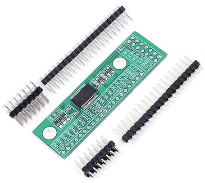
The chip can be used on specifically designed hardware, or a generic module can be used. These are available from several sources.
Note
Due to technical reasons, the MCP23017 rev. D chip no longer has (official) Input capability on the GPA7 and GPB7 pins!
Following this news article, the MCP23017 I2C chip, since revision D released around 2022, might possibly no longer accept signals reliably for Input on the GPA7 and GPB7 pins. Other sources (links no longer available) suggest these pins have had issues taking input signals since at least 2014, so your milage may vary! (Output is still working as usual on these pins.)
This may have impact on the use of this board/chip with this plugin when using a MCP23017 rev. D.
Possible alternatives are using an older revision of this chip, or switching to a different chip, like PCF8574 (8 I/O pins), PCF8575 (16 I/O pins, external pull-up), 74HC165 (Input only), 74HC595 (Output only).
.
Configuration
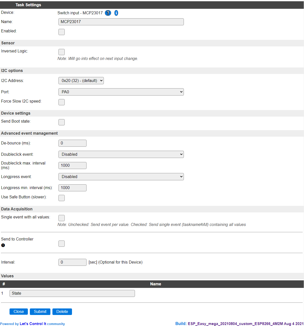
Name A unique name should be entered here.
Enabled The device can be disabled or enabled. When not enabled the device should not use any resources.
Sensor
Inversed Logic When enabled, inverts the input signal, so if the pin is logic high (3.3V), the Value will be 0, and if it is logic low (gnd), the Value will be 1.
I2C Options
The available settings here depend on the build used. At least the Force Slow I2C speed option is available, but selections for the I2C Multiplexer can also be shown. For details see the I2C Bus page
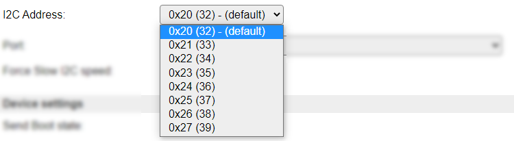
I2C Address: The address the device is using. As there are 8 possible I2C addresses, when the jumpers are configured, the selected value should match with that.
Available options:
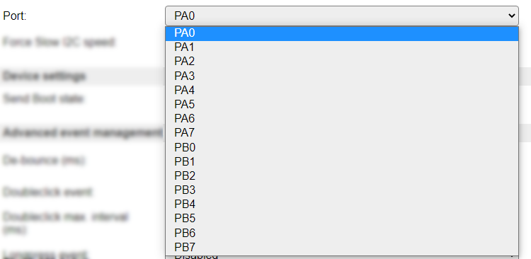
Port As there are multiple Ports available on each board, the desired Port can be selected here.
Available options:
Device Settings
Send boot state: If checked the unit will publish the switch state when booting. If not checked you may find yourself with a latching switch caught in limbo. This means that the unit is registering a low/high value but the physical state of the switch might be the opposite. If you use a mechanical switch that may be physically set to a state you should check this option.
Advanced event management
De-bounce (ms): How long should the pulse (the time you press the button) be, if set to high you need to have it published for a longer time before the unit will register it as an state change. You could experiment with this setting to find a good behavior of the button if you feel that it’s not responding according to your preferences.
Double click event: If enabled the unit will detect double clicks which are within the set interval (see below). The double click event is identified as
MCP23017#State=3. There’s three options for the double click: * Active only on low: the double clicks will be counted by how many low signals that is triggered within the set time. * Active only on high: the double clicks will be counted by how many high signals that is triggered within the set time.Active on high & low: the double clicks will be counted by how many high and low signals that is triggered within the set time. This means that a double click could be registered as a press and release of a button. So not actually double click.
Double click max. interval (ms): This is the interval that you need to perform the double click within.
Long press event: If enabled the unit will detect a long press of a button. There’s three different behaviors of the long press:
Active only on low: this means that the unit will only be triggering the long press event if the signal is low. Two different event values are used,
10if the state goes from 0 to 1 (MCP23017#State=10), and11if the state goes from 1 to 0 (MCP23017#State=11).Active only on high: same as above but only triggered on high signal.
Active on high & low: the long press will be triggered both on high and low signals.
Long press min interval (ms): This is the interval that you need to press the button before the long press event is triggered.
Use safe button (slower): This effectively adds an extra De-bounce delay and sends event value
4when reached.
MQTT Device class
(Only available if both MQTT Auto Discovery and Device Class features are included in the build.)
MQTT Device class: Select the Binary Device class that’s to be used for this task device. Device classes marked with
²are ‘two-way’ devices, meaning that the state will be updated when changed, either on the ESPEasy side, or on the MQTT (Home Assistant) side. For the MQTT Device classesswitchandoutlet, both also marked with÷, the discovery is marked asswitchinstead oflight.
The default value used is switch, also when not set (empty), and can be updated in Home Assistant by resending the MQTT Discovery.
The available options are based on the Summer 2025 version of this Home Assistant MQTT Binary sensor documentation page and also related to this Home Assistant MQTT Switch device page (though that doesn’t document any Auto Discovery information)
The switch device class shows an On/Off icon, the default icon shown for other light or binary_sensor devices in Home Assistant (HA) can be changed for an alternative in the HA configuration, if desired, after Auto Discovery has created the device there.
Data Acquisition
This group of settings are standard available configuration items.
Single event with all values: When this setting is enabled, all available values will be sent in a single event
<TaskName>#All, with all values in order as arguments to the event.Show derived values: When checked, the Devices overview page, and the
/jsonendpoint (used for updating the Devices overview page) will include any Derived values as defined. See theTaskValueSetDerivedandTaskValueSetPresentationcommands.Event & Log derived values: When checked, the Derived values will be generated as Events, to be handled in Rules, and sent to logging devices like the Syslog server and/or SD-card logging.
(The derived values options are only available if String variables feature is included in the build.)
Send to Controller: Select the Controller(s) to send the Values to, either on a
TaskRuncommand applied to the task, or on an Interval time action.
Send to Controller is only visible when one or more Controllers are configured.
Depending on the controller capabilities, some configuration settings may be shown:

All configured Controllers are shown here, including the enabled or disabled state (multiple Controllers can be enabled, only a single MQTT Controller can be enabled at one time!).
For each controller the user can select wether the data should be sent on each Interval (or explicit TaskRun).
For the Domoticz controllers the value index (IDX) has to be configured.
For some controllers, like Home Assistant/openHAB, there are extra options available.
Group: This represents the group id to combine all values from multiple tasks into a single grouped-device during MQTT AutoDiscovery. Groups, by design, can span multiple ESPEasy devices, if desired, as long as the Task/Valuename combinations are unique. If a group should only combine Tasks from a single ESPEasy unit, the group id should be unique across multiple ESPEasy units. The group description, default Group <n>, can be adjusted in Home Assistant. If the Group value matches the current Unit nr, the Unit name,
%sysname%, is used instead of Group <nr>.Retained: For MQTT Controllers, this setting can be enabled to send the values for the current task with the Retain flag set. The Publish Retain flag in the Controller settings will override this by sending all task values with Retain flag enabled.
Send derived: This checkbox determines if any configured Derived values should also be sent to the controller (and included in the AutoDiscovery if that’s available and enabled).
Resend MQTT Discovery: When checked, will start a resend of the MQTT Discovery process for this task after a random delay, when Submit is clicked, so any changed settings will be updated in the MQTT broker. This setting is only available if the controller is enabled, the Auto Discovery feature is available and enabled for the controller. This setting is not stored.
Other controllers, like f.e. FHEM HTTP, do not support additional settings besides the checkbox to enable sending the data.
Interval By default, Interval will be set to 60 sec. It is the frequency used to read sensor values and send these to any Controllers configured for this device.
Values
The name for the value is initially set to a default name, but can be changed if desired.
Commands available
Command (MCPGPIO/Value) |
Extra information |
|---|---|
MCPGPIO: 1 … 128 State: 2 (HIGH-Z, input) 1 (HIGH, output) 0 (LOW, output) -1 (OFFLINE, disconnected) |
Basic on/off.. We can control a pin with simple http URL commands. To change the pin to high or low steady output. Setting MCPGPIO to 2 means that it will be able to detect low level relays (with high impedance, Z). |
MCPGPIO: 1 … 128 |
Toggle on/off.. Toggle the current (output) state of the given MCPGPIO pin. When executed, it changes the pin mode to output. |
MCPGPIO: 1 … 128 State: 1/0 Duration: 1 … 999 S |
To send a *long* pulse to a certain pin.. A long pulse is basically the same as the plain pulse. Duration is defined in seconds, which makes it more suitable for longer duration. This command is not blocking, but will send 2 events to start and stop the pulse. This may have some variation depending on the system load of the module. Variation is typically up-to 10 msec, but may be up-to a second, depending on active plugins and controllers performing blocking operations. |
MCPGPIO: 1 … 128 State: 1/0 Duration: 10 … 15000 msec |
To send a *long* pulse to a certain pin.
A |
MCPGPIO: 1 … 128 State: 1/0 Duration: 0 … 1000 msec |
To send a *short* pulse to a certain pin. Example to send an active high (1) pulse on MCPGPIO 14 for 500 mSeconds. Pulse duration is in milliseconds. State is 1 or 0. N.B. this is a blocking call, meaning no other actions will be performed during the pulse. |
MCPGPIO: 1 … 128 |
Returns the status of a pin. By the use of the command you will receive the status of the relevant pin. |
MCPGPIO: 1 … 128 |
To monitor a MCPGPIO state. By the use of the command you will receive events when the state of that pin is changed from 1 to 0 and from 0 to 1. |
MCPGPIO: 1 … 128 |
To cancel the monitor of a MCPGPIO state. By the use of the command you will stop receiving events when the state of that pin is changed from 1 to 0 and from 0 to 1. |
MCPGPIOfrom/MCPGPIOto: 1 … 128 (end has to be > start) |
To monitor a MCPGPIO state. By the use of the command you will receive events when the state of that pin is changed from 1 to 0 and from 0 to 1. |
MCPGPIO start/MCPGPIO end: 1 … 128 (end has to be > start) |
To cancel the monitor of a MCPGPIO state. By the use of the command you will stop receiving events when the state of that pin is changed from 1 to 0 and from 0 to 1. |
MCPGPIO start pin: 1 … 128
MCPGPIO end pin: 1 … 128 (end has to be > start)
value: 0 or 1
bitmask:
- if not present assume to operate in all pins
- if present is used as a mask (1=update, 0=do not update)
- pins are numbered from right to left (i.e. 87654321)
- if number of bit lower than number of pins, then padded with 0
- if number of bit higher than number of pins, then it’s truncated
|
Change the status of a pin for a given range applying the given mask
examples:
- mcpgpioRange,1,8,1 -> set pins 1 to 8 to 1
- mcpgpioRange,3,12,1 -> set pins 3 to 12 to 1
- mcpgpioRange,5,17,0 -> set pins 5 to 17 to 0
- mcpgpioRange,3,12,1,525 or mcpgpioRange,3,12,1,0b0100001101
mask = ‘0100001101’
write pattern after mask = ‘x1xxxx11x1’ where x indicates that the pin will not be changed
(only pin 1,3,4,9 will be changed)
- mcpgpioRange,3,12,1,973 or mcpgpioRange,3,12,1,0b1111001101
mask = 973 = ‘1111001101’
write pattern after mask = ‘1111xx11x1’ where x indicates that the pin will not be changed
|
MCPGPIO start pin: 1 … 128
MCPGPIO end pin: 1 … 128
write pattern: it’s a write pattern. Write 0 or 1.
- Example: use decimal number 15 (in binary is 00001111) to set to 1 pin 1,2,3 and 4 and to set to 0 pins 5,6,7,8
- if number of bit lower than number of pins, then padded with 0;
- if number of bit higher than number of pins, then it’s truncated.
bitmask:
- if not present assume to operate in all pins
- if present is used as a mask (1=update, 0=do not update)
- if number of bit lower than number of pins, then padded with 0
- if number of bit higher than number of pins, then it’s truncated
|
Change the status of a pin for a given range applying the given mask
examples:
- mcpgpioPattern,1,8,13
write pattern = ‘1101’ that will be padded as: ‘0000001101’
mask not present, assume mask = ‘1111111111’
- mcpgpioPattern,3,12,13
write pattern = ‘1101’ that will be padded as: ‘0000001101’
mask not present, assume mask = ‘1111111111’
- mcpgpioPattern,3,12,525
write pattern = 525 = ‘100001101’
mask not present, assume mask = ‘1111111111’
- mcpgpioPattern, 3, 12, 525, 973
write pattern = 525 = ‘100001101’
mask = 973 = ‘1111001101’
write pattern after mask = ‘1000xx11x1’ where x indicates that the pin will not be changed
|
MCPGPIO: 1 … 128
mode:
0 = OUTPUT
1 = INPUT PULLUP
2 = INPUT
|
To change the mode of an MCPGPIO pin. example: mcpMode,1,0 (set pin 1 as output)
|
MCPGPIO start pin: 1 … 128
MCPGPIO end pin: 1 … 128 (end has to be > start)
mode:
0 = OUTPUT
1 = INPUT PULLUP
2 = INPUT
|
To change the mode of an MCPGPIO range of pin. example: mcpModeRange,1,8,0 (set pin 1 to 8 as output)
|
Change log
Changed in version 2.0: …
changed 2021-08-04 Replaced single Port inputfield with separate I2CAddress and Port selections.
added Major overhaul for 2.0 release.
Added in version 1.0: …
added Initial release version.