DS18B20 and compatible Temperature sensors
Introduction
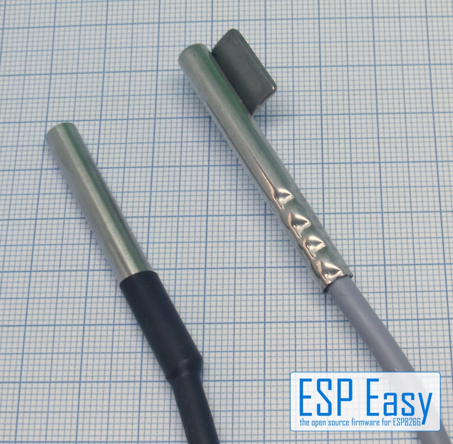
This plugin supports up to 4 1-Wire Temperature sensors, and closely related sensor types, like DS18B20, DS1820/DS18S20, DS1822, DS1825, DS28AE00 and MAX31826.
Note
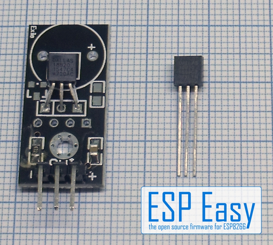
Beware of cheap remakes from the Chinese market. They might have wider tolerance and/or different pinouts. The DS18B20 manufactured by Dallas and Maxim is a very simple to use temperature sensor with a tolerance of ±0.5°C.
Its advantages: Very simple to use due to “1-wire” data protocol. Chainable, it is possible to chain up to 100 sensors on one cable (remember ESP Easy has 12 tasks max…). No calibration necessary if the tolerance fits your needs as the sensor gives digital data directly. Many forms available from bare chip to waterproof and tube sensors.
- Specifications:
Temperature (-55C to +125C)
Voltage requirements: 3.3-5V
Note
The DS18B20 runs well on 3.3V so no level shifter or special power supply is needed. But the official statement is that you should use 5V and a level shifter if you have multiple sensors on a long wire.
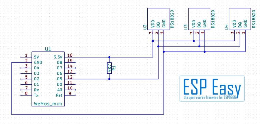
Wiring
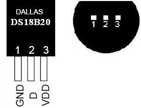
ESP               DS18b20
GPIO (14)  <-->   1-wire/D (yellow)

Power
3.3/5.0V   <-->   VDD (red)
GND        <-->   GND (black)
The sensor needs a pull up resistor. If you use the breakout board type the resistor usually is already on the board. This gets you into problems if using several DS18B20 breakout boards. There should be only one resistor for the entire line so you might have to remove resistors leaving just one at one end of the line.
Typical value for the pull up resistor is 4k7 ohms. For multiple sensors on the same wire this value may need to be lowered a bit.
Do not use very thin cabling! Tested with a 3x0.14mm² cable the length with 5 Sensors was 10 meters, longer cabling did not work. Use a phone line cable (2x2x0.6mm²) instead if you need long distances up to 50..100 meters. Remember: Use only one pull-up resistor for the whole line!
The preferred structure is a straight line. If possible avoid “stubs”. If necessary it can be cabled in a “star” infrastructure. But be aware that stubs and star form reduce the possible cable length.
Setup
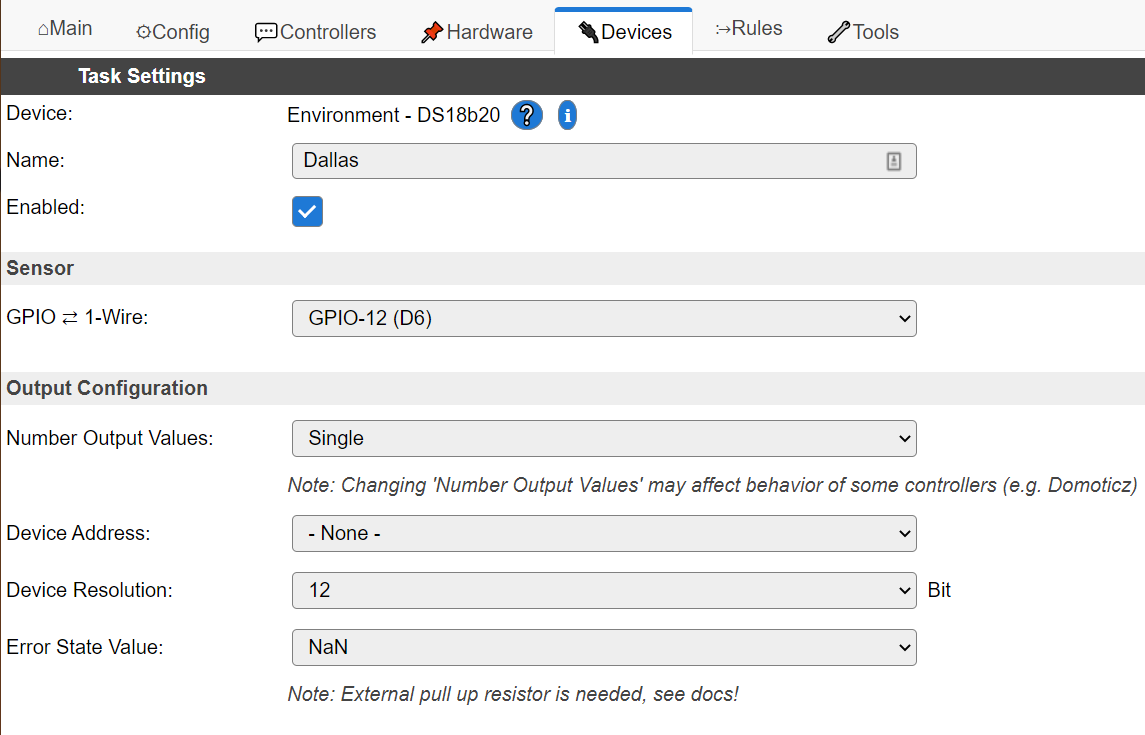
Task settings
Device: Name of plugin
Name: Name of the task (example name TempN, where N is a number).
Enable: Should the task be enabled or not
Sensor
GPIO <–> 1-wire
Pin used for communicating with the Dallas sensor(s). This is the single wire setup so you can leave the TX GPIO empty or set it equal to the RX GPIO.
Please note the pin must be pulled up by a resistor, so only use pins that can be in a pulled up state during boot (thus NOT use GPIO 15 on ESP8266).
GPIO <–> Shelly Temperature add-on
The Shelly temperature add-on requires a two wire setup. Set TX to GPIO 3 and RX to GPIO 0.
Please note GPIO 3 is normally used by Serial 0 which is enabled by default. You might run into issues when not disabling the Serial port first (Tools > Advanced > Enable Serial port).
Number Output Values
(Added 2020-11-16)
Selector to set number of Dallas sensors for this task.
Number of address selectors is based on the set Number Output Values.
If more then one sensor is set to a task, all sensors will be sent a start measurement command in the order they are selected. After the expected reading period (depending on the set resolution) the sensors will be read in the same order.
This means their measurement period overlap, which can be of great use to make sure the temperature values are taken at the same moment.
Not all controllers can handle reading multiple sensors in a single run. For example you cannot send directly to Domoticz controllers running multiple sensors in the same task. If it is still needed to have multiple sensors in the same task, one can still send the data via rules to Domoticz.
Note
Interleaved reading of multiple sensors on a task can only be done if the sensors are powered via their Vdd pin. Parasite powered sensors are not supported in this mode.
Auto Select Sensor
(Added 2022-10-16)
This allows for “auto configuration” only when using a single sensor on the configured pin(s). During init of the task, the task will scan the 1-Wire bus and just pick the first found sensor (the one with the lowest address).
Typical use case is to allow for easy replacing the sensor without the need to reconfigure the task.
Device address
Selector for a specific sensor address.
If a found sensor is already assigned (and saved) to a task, the task name and variable name is shown in the combo box. (Added 2020-11-16)
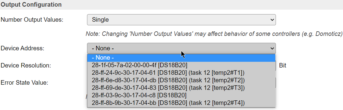
Note
It may be hard to keep these addresses apart. Either add them one by one, or heat up a single one by holding it in your hand. When the web page for a Dallas temperature task is loaded the bus is scanned thus newly attached sensors will then show up in the list.
Device resolution
Possible values: 9..12 bits
The resolution determines the time needed for taking a measurement. At 12 bit resolution a measurement takes roughly 800 msec.
As temperatures do not change very fast usually a high accuracy can be chosen without problem.
N.B. resolution applies to all sensors for this task.
N.B. Some sensors, like the MAX31826, have a fixed resolution. The command to change te resolution is not sent to that sensor-type (Added 2023-04-16).
Error State Value
Select the value to send if the sensor could not be read.
Almost all controllers will not send values if the value is NaN.
By chosing a specific value one can make sure values are sent.
Statistics
Dallas 1-wire sensors may sometimes return a read error. A typical setup running Dallas sensors on ESPEasy should have less than 1-in-1000 reads fail.
A failed read attempt will be replaced by the set value of the Error State Value.
The number of read errors may depend on a number of factors, like cabling or using non genuine sensors.
Some known counterfeit sensors are known to cause problems when used with > 3 on the same bus. Others always report being “Parasite Powered” while they are not.
The Statistics can help determining why a setup of sensors may not perform as well as it should.
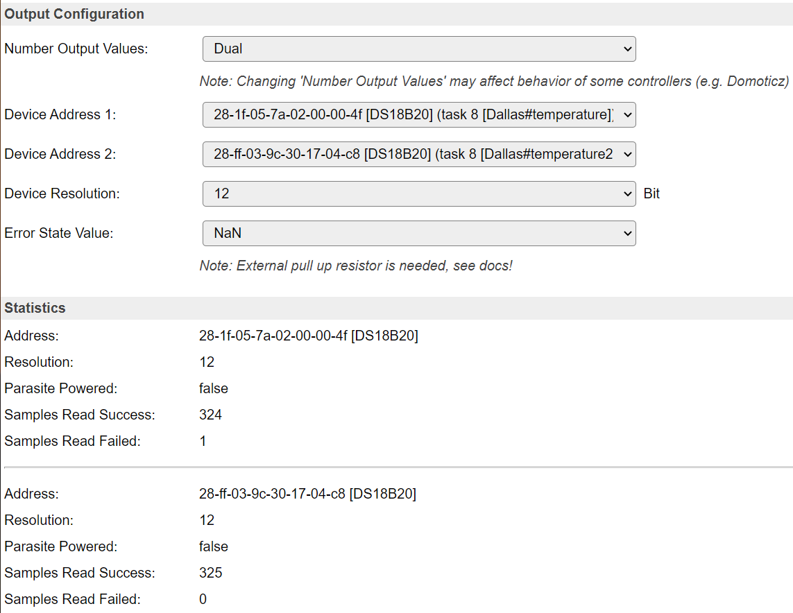
Note
Because of the issues that can arise from these sensors being used with parasitic power (via the data line), this configuration, while it may work, is unsupported, and a matching warning message is shown if Parasite Powered is reported true by the sensor.

Note
If you need a star infrastructure or stubs or if you need just longer cabling there is a way out. One line runs on one GPIO. But nobody said you can’t use two GPIO’s. If the cabling gets too long or you have too much stubs or star cables try to split into two circuits. Place the ESP in the mid and cut the line into two circuits, for example “Ground Floor” and “1st Floor”. Use two GPIO’s, one for each circuit.
Note
Usually the DS18B20 works without issues. It’s also usual that most problems result from cabling mistakes. With long cabling you might get wrong data sometimes. It might be helpful to reduce the resistor a bit, 2.2 kOhm is lowest possible. If nothing works disconnect all sensors from line and connect back one by one, checking every time. Cable may be too long (or too thin for the given distance). Keep cabling away from other cables to avoid interferences. If necessary place a 10µF capacitor on the sensors between 3.3v and GND.
Data Acquisition
This group of settings are standard available configuration items.
Single event with all values: When this setting is enabled, all available values will be sent in a single event
<TaskName>#All, with all values in order as arguments to the event.Show derived values: When checked, the Devices overview page, and the
/jsonendpoint (used for updating the Devices overview page) will include any Derived values as defined. See theTaskValueSetDerivedandTaskValueSetPresentationcommands.Event & Log derived values: When checked, the Derived values will be generated as Events, to be handled in Rules, and sent to logging devices like the Syslog server and/or SD-card logging.
(The derived values options are only available if String variables feature is included in the build.)
Send to Controller: Select the Controller(s) to send the Values to, either on a
TaskRuncommand applied to the task, or on an Interval time action.
Send to Controller is only visible when one or more Controllers are configured.
Depending on the controller capabilities, some configuration settings may be shown:

All configured Controllers are shown here, including the enabled or disabled state (multiple Controllers can be enabled, only a single MQTT Controller can be enabled at one time!).
For each controller the user can select wether the data should be sent on each Interval (or explicit TaskRun).
For the Domoticz controllers the value index (IDX) has to be configured.
For some controllers, like Home Assistant/openHAB, there are extra options available.
Group: This represents the group id to combine all values from multiple tasks into a single grouped-device during MQTT AutoDiscovery. Groups, by design, can span multiple ESPEasy devices, if desired, as long as the Task/Valuename combinations are unique. If a group should only combine Tasks from a single ESPEasy unit, the group id should be unique across multiple ESPEasy units. The group description, default Group <n>, can be adjusted in Home Assistant. If the Group value matches the current Unit nr, the Unit name,
%sysname%, is used instead of Group <nr>.Retained: For MQTT Controllers, this setting can be enabled to send the values for the current task with the Retain flag set. The Publish Retain flag in the Controller settings will override this by sending all task values with Retain flag enabled.
Send derived: This checkbox determines if any configured Derived values should also be sent to the controller (and included in the AutoDiscovery if that’s available and enabled).
Resend MQTT Discovery: When checked, will start a resend of the MQTT Discovery process for this task after a random delay, when Submit is clicked, so any changed settings will be updated in the MQTT broker. This setting is only available if the controller is enabled, the Auto Discovery feature is available and enabled for the controller. This setting is not stored.
Other controllers, like f.e. FHEM HTTP, do not support additional settings besides the checkbox to enable sending the data.
Interval: How often should the task publish its value (5..15 seconds is normal).
Values
Name: Value Name of temperature indicator.
Formula: Optional math conversion. The measured temperature defaults to Celsius. It can be converted to Fahrenheit by entering this formula:
(%value%*9/5)+32
Indicators (recommended settings)
Indicator |
Value Name |
Interval |
Decimals |
Extra information |
|---|---|---|---|---|
Temperature |
Celsius |
10 |
1 |
Rules examples
On Temperature1#Celsius Do
 If %eventvalue1%>37
   NeoPixelAll,255,0,0 //Your body temperature is too high!
 Else
   NeoPixelAll,0,255,0 //Body temperature is OK.
 EndIf
EndOn
Where to buy
Store |
Link |
|---|---|
AliExpress |
|
Banggood |
|
eBay |
$ = affiliate links which will give us some money to keep this project running, thank you for using those.
More pictures