Environment - BMx280
Temperature and pressure for the BME280 and BMP280 sensors.
Plugin details
Type: Environment
Name: BMx280
Status ESP32: NORMAL CLIMATE
Status ESP8266: NORMAL CLIMATE
GitHub: P028_BME280.ino
Maintainer: .
Used libraries: .
Supported hardware
Introduction
- Specifications:
Temperature (-40C to +85C)
Relative humidity (0-100 %RH) (Only available from BME280 sensor)
Barometric pressure (300-1100 hPa)
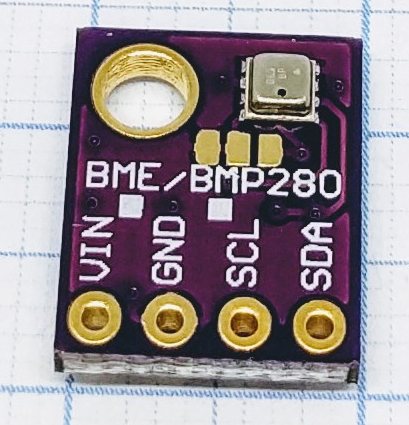
Warning
The BME280 is easily mistaken for its sibling the BMP280. Sometimes the PCB have both BME and BMP280 written on it, it’s probably because the footprint is the same for BME and BMP = the same PCB board is used by both. Luckily, this plugin supports both types of sensors.
Wiring
ESP               BMx280
GPIO (4)   <-->   SDA
GPIO (5)   <-->   SCL

Power
3.3V       <-->   VIN
GND        <-->   GND
Note
If you have changed the I2C settings in the hardware setup you need to connect to those instead of GPIO 4 and 5.
Configuration
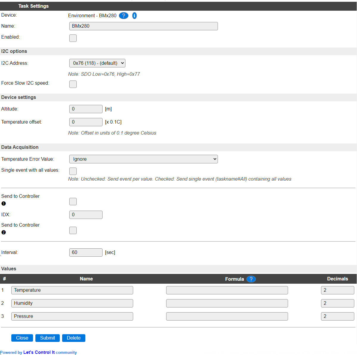
Name A unique name should be entered here.
Enabled The device can be disabled or enabled. When not enabled the device should not use any resources.
I2C Options
The available settings here depend on the build used. At least the Force Slow I2C speed option is available, but selections for the I2C Multiplexer can also be shown. For details see the I2C Bus page
I2C Address: The address the device is using. Depending on the board used, when available a SDO pin, or soldering a 0 ohm resistor on a different location, can be used to select the used address. If that address selection is not available, then an I2C multiplexer (in a matching ESPEasy build) can be used to use multiple sensors on a single ESPEasy unit. Below are instructions for selecting the alternate address.
Device Settings
Altitude When not at sea-level, the plugin can apply an altitude compensation on the Pressure value.
Temperature offset Depending on the sensor and the location of the sensor, it may be required to apply some temperature compensation. This can be set in steps of 0.1 degree. When using a BME280 sensor, this also applies a compensation to the Humidity reading.
Data Acquisition
This group of settings are standard available configuration items.
Single event with all values: When this setting is enabled, all available values will be sent in a single event
<TaskName>#All, with all values in order as arguments to the event.Show derived values: When checked, the Devices overview page, and the
/jsonendpoint (used for updating the Devices overview page) will include any Derived values as defined. See theTaskValueSetDerivedandTaskValueSetPresentationcommands.Event & Log derived values: When checked, the Derived values will be generated as Events, to be handled in Rules, and sent to logging devices like the Syslog server and/or SD-card logging.
(The derived values options are only available if String variables feature is included in the build.)
Send to Controller: Select the Controller(s) to send the Values to, either on a
TaskRuncommand applied to the task, or on an Interval time action.
Send to Controller is only visible when one or more Controllers are configured.
Depending on the controller capabilities, some configuration settings may be shown:

All configured Controllers are shown here, including the enabled or disabled state (multiple Controllers can be enabled, only a single MQTT Controller can be enabled at one time!).
For each controller the user can select wether the data should be sent on each Interval (or explicit TaskRun).
For the Domoticz controllers the value index (IDX) has to be configured.
For some controllers, like Home Assistant/openHAB, there are extra options available.
Group: This represents the group id to combine all values from multiple tasks into a single grouped-device during MQTT AutoDiscovery. Groups, by design, can span multiple ESPEasy devices, if desired, as long as the Task/Valuename combinations are unique. If a group should only combine Tasks from a single ESPEasy unit, the group id should be unique across multiple ESPEasy units. The group description, default Group <n>, can be adjusted in Home Assistant. If the Group value matches the current Unit nr, the Unit name,
%sysname%, is used instead of Group <nr>.Retained: For MQTT Controllers, this setting can be enabled to send the values for the current task with the Retain flag set. The Publish Retain flag in the Controller settings will override this by sending all task values with Retain flag enabled.
Send derived: This checkbox determines if any configured Derived values should also be sent to the controller (and included in the AutoDiscovery if that’s available and enabled).
Resend MQTT Discovery: When checked, will start a resend of the MQTT Discovery process for this task after a random delay, when Submit is clicked, so any changed settings will be updated in the MQTT broker. This setting is only available if the controller is enabled, the Auto Discovery feature is available and enabled for the controller. This setting is not stored.
Other controllers, like f.e. FHEM HTTP, do not support additional settings besides the checkbox to enable sending the data.
Temperature Error Value If no sensor is connected, or the sensor suffers from read errors for some reason, the Temperature value to report in that situation can be set here. Both Humidity and Pressure will be set to -1 when such read errors occur.
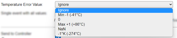
Ignore : Do not return any value (does log the error once per second at INFO level).
Min -1 (-41C°) : Set to the out-of-range value, below sensor minimum, of -41°C.
0 : Set to an unknown value of 0.
max +1 (+85°C) : Set to the out-of-range value, above sensor maximum, of 86°C.
NaN : Set to the error value
NaN(Not a number).-1°K (-274°C) : Set to the impossible temperature value of -1° Kelvin.
The Temperature range of the sensor, according to the datasheet, is -40 to +85 °C, so the out of range values of -41 and +86 can be selected as error state values.
Single event with all values, Send to Controller and Interval settings are standard available configuration items. Send to Controller only when one or more Controllers are configured.
Interval By default, Interval will be set to 60 sec. The minimum value allowed is 1 sec.
Data Source
Note
The Data Source section is only available when the task is configured to receive data from a remote node!
When using Controller - ESPEasy P2P Networking and having multiple ESP nodes using the same ESPEasy p2p UDP port (see the Tools/Advanced page, default: 8266, IANA registered), you can receive values from a remote node with the same plugin active. How to configure this is documented in the P2P Controller page.
In a regular configuration, having the sensor connected locally, the plugin auto-detects what type of sensor is used, either BME280 or BMP280, and auto-adjusts the values supported. When receiving data from the P2P network, this ‘setting’ is verified and must match on the receiving end of the P2P connection. This information is not included in the P2P protocol data, so a configuration option is available, only shown if the task is configured to receive remote data.
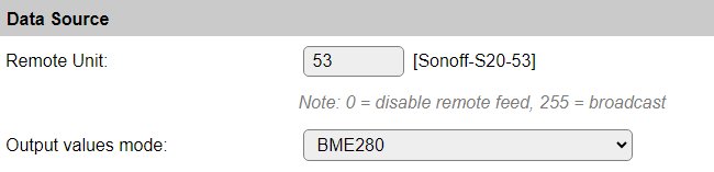
Remote Unit: Shows the unit number and name the data is received from.
Output values mode: Allows selection of the sensor that is installed on the sending unit (node).
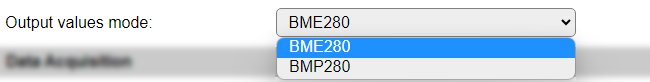
Available options:
BME280: Sending node has a BME280 sensor, will provide the Temperature, Humidity and Pressure values.
BMP280: Sending node has a BMP280 sensor, will provide the Temperature and Pressure values.
Values
The measured values are available in Temperature, Humidity and Pressure. A formula can be set to recalculate. The number of decimals is by default set to 2, and can be set to 0 for Humidity and Pressure, as no decimals are provided from the measurement.
Note
When a BMP280 sensor, that provides only Temperature and Pressure data, is connected, the Humidity value will still be visible, but show 0.
Rules examples
on BME#Pressure do
  if %eventvalue1%>999
    Publish,%sysname%/pressure,Is normal
  endif
endon
Change I2C address
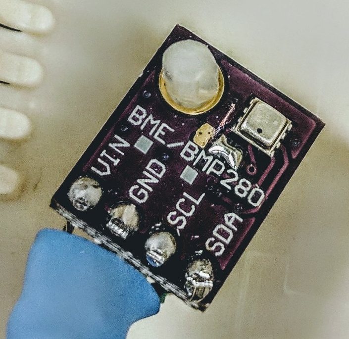
You may change the i2c address from the default 0x76 to 0x77 by cutting the line between the two left pads (as seen in the pictures below) and solder a bridge between the two right pads.
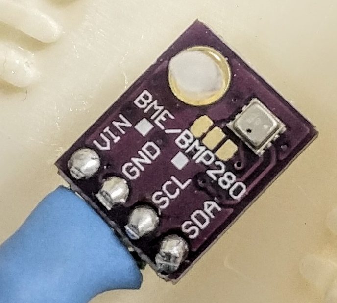
Default i2c address 0x76.
Changed i2c address 0x77.
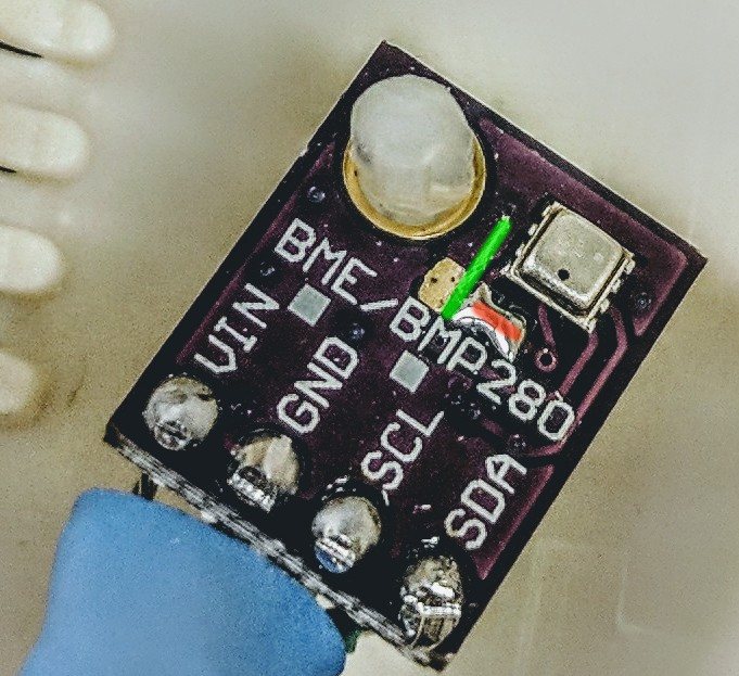
Cut Solder/bridge
Change log
Changed in version 2.0: …
added 2022-05-10 Added Error State Value option, documentation overhaul.
added Major overhaul for 2.0 release.
Added in version 1.0: …
added Initial release version.