Environment - Thermosensors
.
Plugin details
Type: Environment
Name: Thermosensors
Status ESP32: NORMAL CLIMATE
Status ESP8266: NORMAL CLIMATE
GitHub: P039_Thermosensors.ino
Maintainer: .
Used libraries: .
.
Change log
Changed in version 2.0: …
added Major overhaul for 2.0 release.
Added in version 1.0: …
added Initial release version.
Description
This Plugin reads the data from Thermocouples and Resistor Temperature Detector sensors. You have to use an Adapter Board with a respective adapter/converter in order to read the values. Take a look at the usual sources to find such boards.
You can use any board which expose the SPI Interface. This Plugin uses only the selected SPI Interface. Nevertheless you need at least 3 Pins to use SPI. So using an very simple ESP-01 is unfortunately no option.
Basic Information on Thermocouples Wikipedia: Thrmocouples
Basic Information on Resistor Temperature Detector Sensors Wikipedia: Resistance Thermometers
Wiring
Basic Information on SPI Bus you can find in Wikipedia: SPI Bus
You need an ESP8266 device with accessible SPI Pins. These Pins are:
Name |
Description |
PIO |
NodeMCU |
Notes |
|---|---|---|---|---|
MOSI |
Master Output |
GPIO13 |
D7 |
Hardware SPI (only required in case of write access to device registers) |
MISO |
Master Input |
GPIO12 |
D6 |
Hardware SPI |
SCK |
Clock Output |
GPIO14 |
D5 |
Hardware SPI |
CS |
Chip Select |
GPIO15 |
D8 |
Hardware SPI (CS is configurable through the web interface) |
Note
Write Access to device registers is required for MAX 31856 and MAX 31865 devices so far.
For ESP32 you can use any VSPI, HSPI or User Defined configuration, as the GPIO multiplexer in ESP32 chips can handle any GPIO pin with Input and Output capability for SPI.
Supported Hardware
[2021-05-03]: Added support for RTD sensor adapters based on Maxim Device MAX21865.
This adapter device requires write access to internal configuration registers. For this device you will need to wire MOSI signal to your adapter. For MAX31865 multiple shields are available in the usual sources. Those are mostly based on Adafruit MAX 31865 shield and follow the original schematics and element values.

The adapter can be purchased prepared for the required senor type (PT 100 or PT 1000). Basically this will influence the choice of the reference resistor. Those resistors are usualy chosen with the following values, but can be adjusted to the needs of the user and the application.
Sensor Type
Reference Resistor Value
PT 100
Rref = 430 Ohm
PT 1000
Rref = 4300 Ohm
The populated value can be directly stated in the device configuration and therefore adjusted to any desired resistor value.
The modules often allow usage of 2-wire, 3-wire and 4-wire connection of an appropriate sensor. For activation of the connection type, it requires closing/opening of hardware bridges on the adapter and adjustment of the configuration in the ESPEasy device configuration.
MAX31865 devices support filtering of noise frequencies resulting from the frequency of your power net. Basic filtering of 50/60 Hz noise contributions can be adjusted in the device configuration. See configuration examples below.
[2021-02-xx]: Initial support of thermocouple sensors via Maxim devices MAX6675, MAX31855 and MAX31856
From the start this device allows usage of thermocouple sensors and adapters. Most of them are rather simple to use and access, as they only require read access to their SPI interface. Nevertheless they provide powerful options to sense high temperature ranges and difficult sensing scenarios. See system advantages and limitations on above mentioned Wikipedia page on Thermocouples.

Depending on the type of adapter used, you will either have to chose the device according to the used sensor type (MAX6675/MAX31855 -> B, E, J, K, …) or you can configure the sensor type in ESPEasy configuration page (MAX31856).

Configuration in ESPEasy
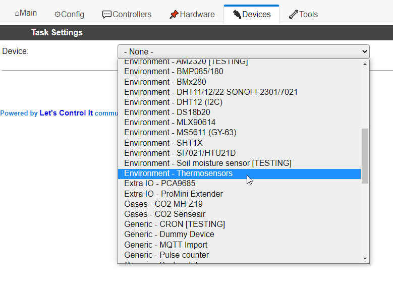
Within ESPEasy tab “Devices” chose the plugin “Environment - Thermosensors” to use the plugin.
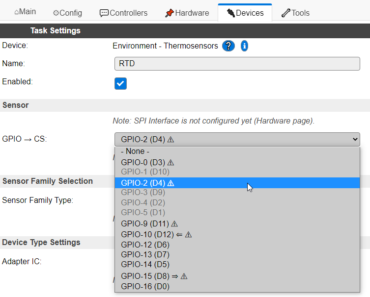
In the plugin configuration page you will be initially asked to define the unique name of the task and the CS pin used for activating the SPI communication.
At first you need to select the name of the task and the GPIO pin you want to use as CS for your SPI interface. You can select every GPIO that is not blocked by another device or which is limited by its function capabilities, e.g. not possible to configure as OUTPUT.
Keep in mind some of the GPIOs require dedicated states during boot or have limited configuration options. E.g. D8 need to be pulled to GND during boot to allow proper boot. Some of the shields provide 10k pull-up resistors overriding any weak pull-down on an ESP 8266 and such avoid correct start up of ESP. In such cases solder an additional 4,7k resistor between GND and D8.
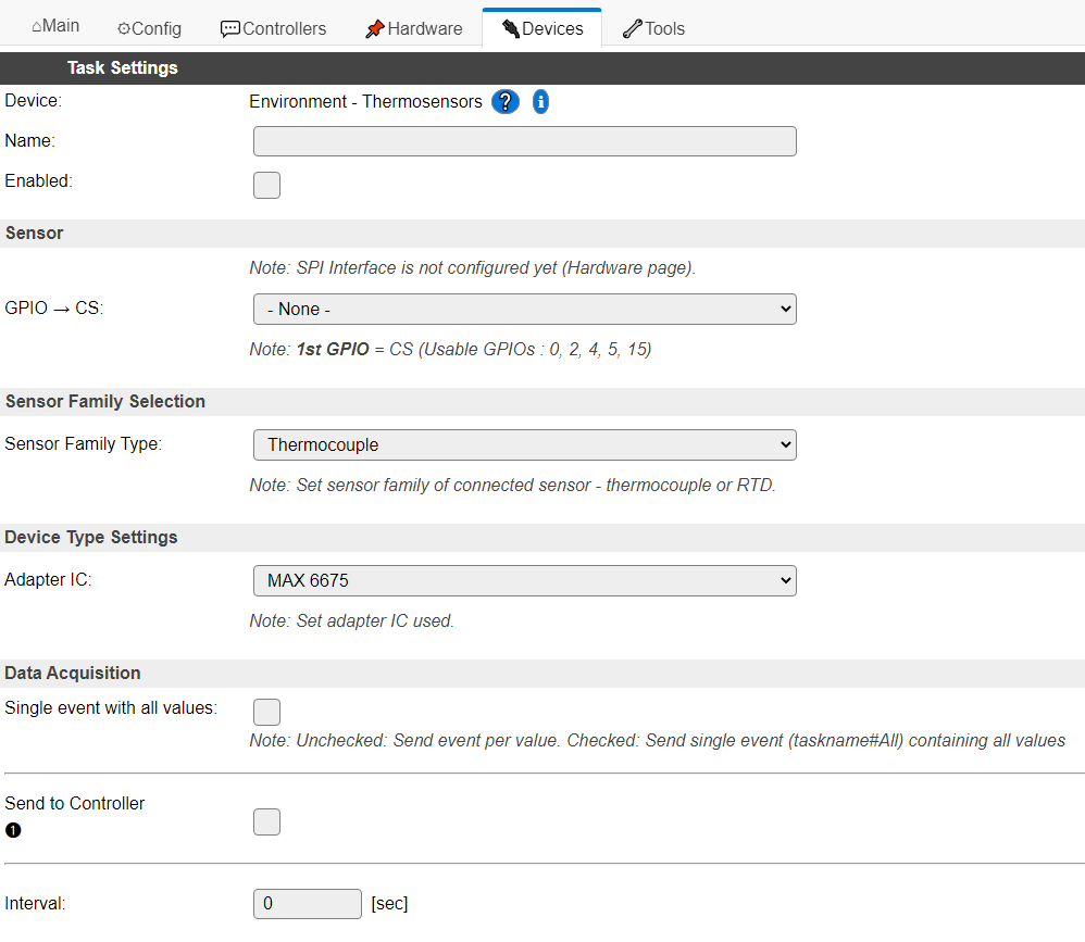
After that, the configuration page of the device provides a three step configuration:
Choose the type of sensor you want to use
Inital configuration step is to decide on which sensor family you want to use. This device support two:
Thermocouple –> Thermocoupling Sensors
RTD –> Resistor Temperature Device Sensors
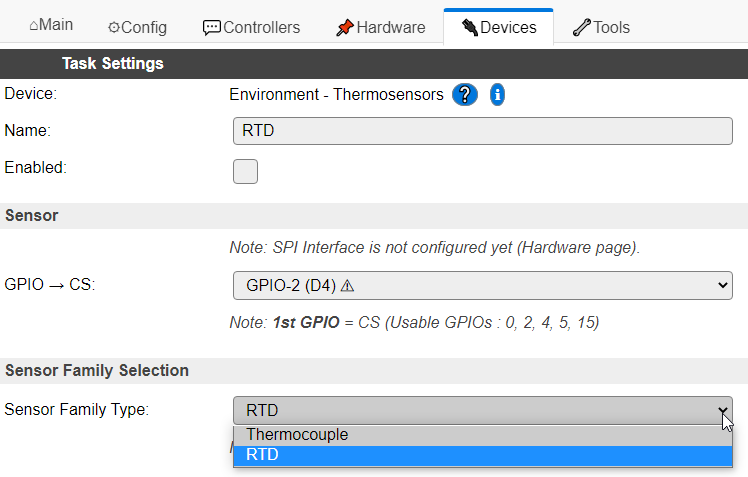
With the drop down field you can chose the sensor type you want to use.
Choose the type of the adapter device you use
In case you want to use RTD adatpers the further configuration looks like the following:
When page has been updated after the submit you can decide on which adapter device you plan to use.
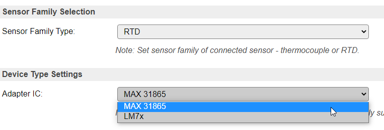
Depending on the chosen sensor type the drop box will adjust the possible choices to the supported devices
Configure the device details to match your needs
When page has been updated after the submit you can configure the device according to your needs.
In this section you can detail the configuration to adjust the behavior to your technical needs.
After this selection select the enable check box in the upper section of this configuration page and submit the configuration to finalize the set up.
Details on Device Settings
MAX 6675, MAX 31855
For these two devices there is no further device settings needed.
MAX 31856
For this device currently three parameters can be selected:
Type of thermocouple used with the device
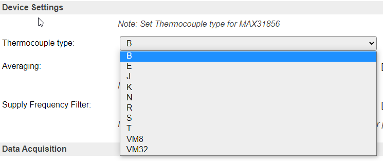
MAX 31856 supports multiple types of thermocouples to be used with the adapter. This allows optimum choice of the sensor according to the measured temperature range. The following types of thermocouples are supported:
TYPE
T-WIRE
T+ WIRE
TEMP RANGE
NOMINAL SENSITIVITY (μV/°C)
COLD-JUNCTION TEMP RANGE
B
Platinum/Rhodium
Platinum/Rhodium
250°C to 1820°C
10.086 (+500°C to +1500°C)
0 to 125°C
E
Constantan
Chromel
-200°C to +1000°C
76.373 (0°C to +1000°C)
-55°C to +125°C
J
Constantan
Iron
-210°C to +1200°C
57.953 (0°C to + 750°C)
-55°C to +125°C
K
Alumel
Chromel
-200°C to +1372°C
41.276 (0°C to + 1000°C)
-55°C to +125°C
N
Nisil
Nicrosil
-200°C to +1300°C
36.256 (0°C to +1000°C)
-55°C to +125°C
R
Platinum
Platinum/Rhodium
-50°C to +1768°C
10.506 (0°C to +1000°C)
-50°C to +125°C
S
Platinum
Platinum/Rhodium
-50°C to +1768°C
9.587 (0°C to +1000°C)
-50°C to +125°C
T
Constantan
Copper
-200°C to +400°C
52.18 (0°C to +400°C)
-55°C to +125°C
Most commonly used type is Type “K”, as it provides wide temperature range with medium/good sensitivity at reasonable prices.
Using “Unsupported” Thermocouple Types
To use a thermocouple type other than B, E, J, K, N, R, S, or T, select one of the voltage mode options from the following table. Selecting “VM8” results in a full-scale input voltage range of ±78.125mV. “VM32” results in a full-scale input voltage range of ±19.531mV. See the transfer functions from the table below. When voltage mode is selected, no linearization is performed on the conversion data. Use the voltage data and the cold-junction temperature to calculate the thermocouple’s hot-junction temperature.
Mode
Short Description
Transformation Formula
VM8
Voltage Mode, Gain = 8
Code = 8 x 1.6 x 2 17 x V in
VM32
Voltage Mode, Gain = 32
Code = 32 x 1.6 x 2 17 x V in
Note
Code is 19 bit signed number from TC registers and VIN is thermocouple input voltage. The plugin directly provides V in value. TC Range failure bit (SR register, Bit 6) is ignored when using these modes.
Averaging Factor
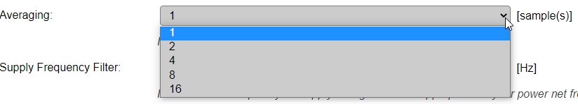
MAX31856 supports on chip averaging of multiple measurement values. The number of measurements averaged to a result can be configured with this value. The device supports several modes.
Mode
Short Description
Effect*
1
1 sample (default)
no averaging
2
2 samples averaged
up to 185ms + 40ms conversion time
4
4 samples averaged
up to 185ms + 120ms conversion time
8
8 samples averaged
up to 185ms + 280ms conversion time
16
16 samples averaged
up to 185ms + 600ms conversion time
Note
see data sheet on more details. Conversion takes place in between read cycles.
Adding samples increases the conversion time and reduces noise. Typical conversion times:
- 1-shot or first conversion in Auto mode:
= t :subscript::CONV + (samples -1) x 33.33mS (60Hz rejection) = t :subscript::CONV + (samples -1) x 40mS (50Hz rejection)
- 2 thru n conversions in Auto mode
= t :subscript::CONV + (samples -1) x 16.67mS (60Hz rejection) = t :subscript::CONV + (samples -1) x 20mS (50Hz rejection)
Note
t CONV max. = 185ms according to MAX31856 datasheet.
Selection of Power Net Filter
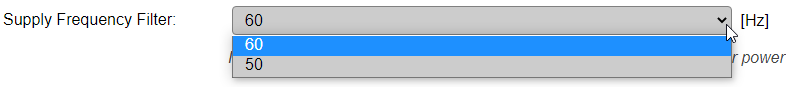
Last but not least you need to select the power net filter according to the frequency of your local power net.
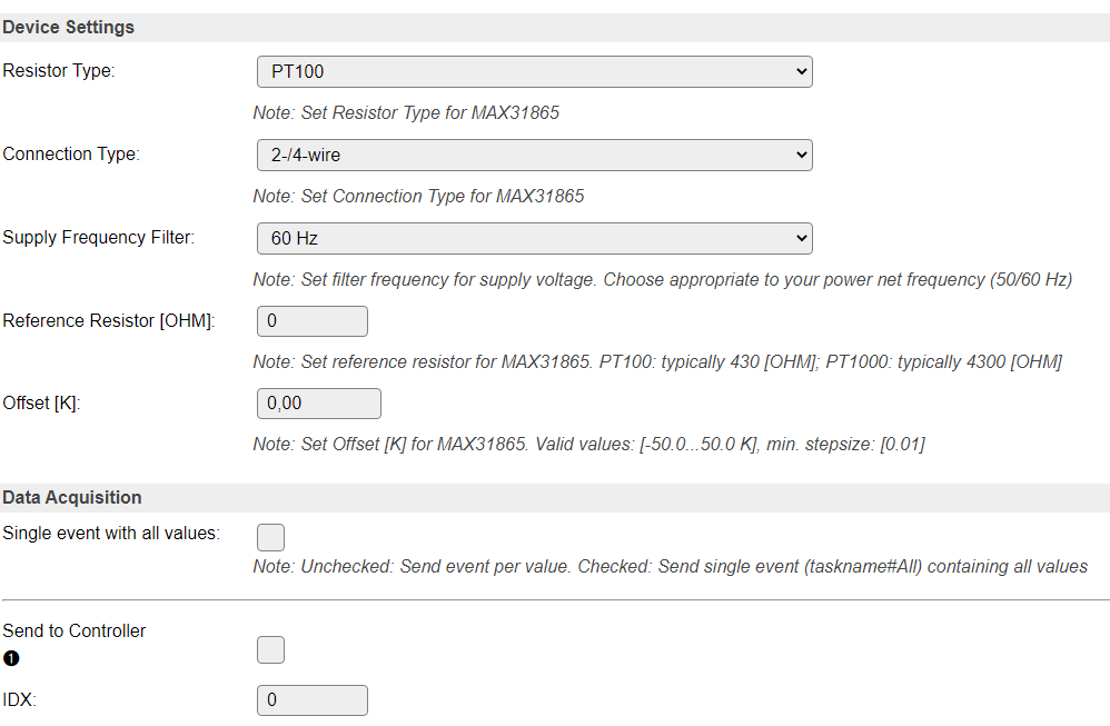
MAX 31865
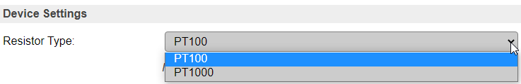
For MAX 31865 you can define the sensor according to its resistor value given at 0°C / 32°F.
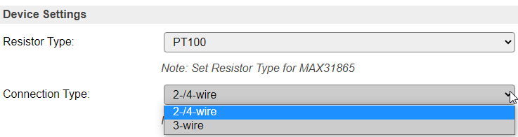
Select the sensor wiring you plan to use with your RTD sensor - 2-/4-wire or 3-wire
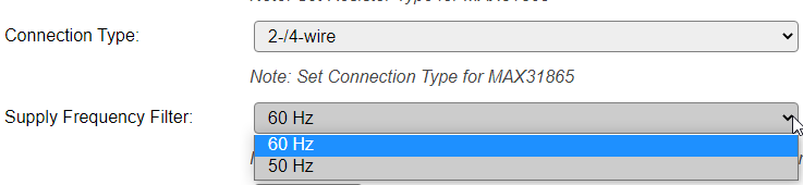
After that you need to select the power net filter according to the frequency of your local power net
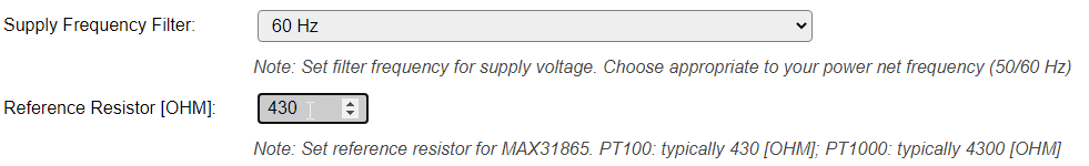
For this box you need to define the value of your reference resistor.

In this configuration box you can define an offset value which is added to the sensor result. It can be negative/positiv value and can be given with 0.01 K accuracy.
LM 7x
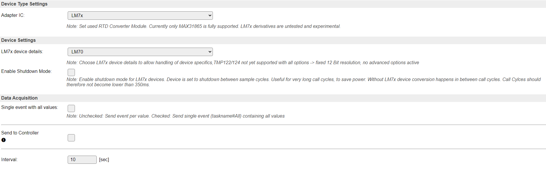
For LM7x device family you have multiple options to be configured.
Note
At the given point in time LM7x device family is only supported experimental. Communication is tested to be present, but correct reading of values is not proven, due to missing hardware for testing.
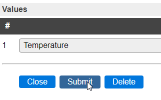
Value validation
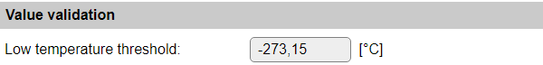
Low temperature threshold: To avoid sending out unrealistic temperatures when the sensor is still initializing and not yet returning valid temperatures, a Low threshold can be configured, that will result in lower values not being seen (and sent to controllers) as valid. Default is 0 K (-273.15°C) and the max. allowed input is 1000.0°C
Generic Plugin Configuration
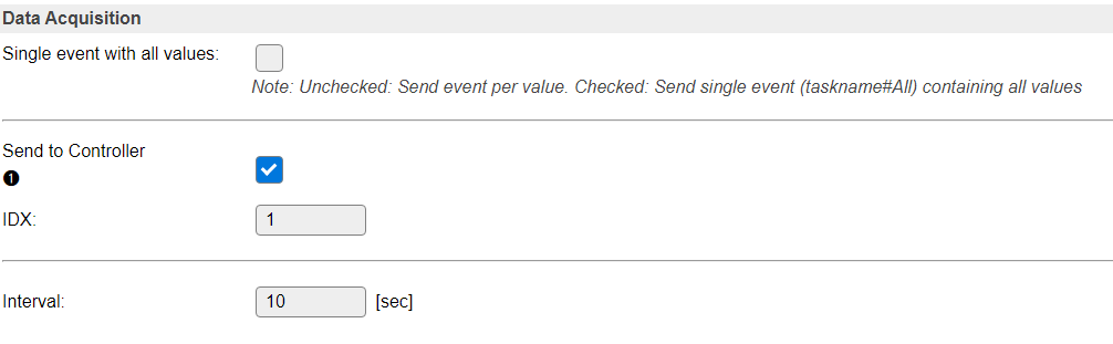
Finally the plugin requires configuration of DAQ Mode and you can activate the communication to an exisiting controller from the ESPEasy “Controller” Tab.