tSense (K70)
Gases - CO2 Senseair NORMAL CLIMATE
Introduction
Using the plugin P052 Senseair you can use the tSense (K70) as a sensor for temperature, humidity and carbon dioxide. You can even use it to monitor the status of the internal relay, or control the relay as well. If you have the EFA version of the tSense the temperature adjustment is also possible to monitor.
The standard model of tSense display temperature, humidity and carbon dioxide level on the main page. The relay can only be set to trigger by the settings menu where you can have a target level where the relay will activate.
Note
For both models the user password for the settings is by default “1111” and for the advanced settings level the password is “2001”.
- Specifications:
0 to 2000 ppm
12VDC, 24VAC/DC
UART communication (Modbus (MB) or BACnet (BAC) protocol over RS485)
15 years life span
No burn-in needed, will stabilize after 8 days at worst depending on placement environment
Warning
CONNECTING THIS PLUGIN WILL VOID THE WARRANTY OF YOUR tSENSE!
Wiring
ESP               tSense
GPIO (7)   <-->   TX (see pictures further down)
GPIO (8)   <-->   RX (see pictures further down)

Power
5.0V       <-->   VCC (see pictures further down)
GND        <-->   GND (see pictures further down)
Set up the K70 according to this simple schematics. If you want to take extra precautions you should add 47R resistor or similar to the TX and RX signals (this is not used in the pictures below). In this example we use the Wemos D1 mini and piggy back the power from the K70 5V via.
Setup
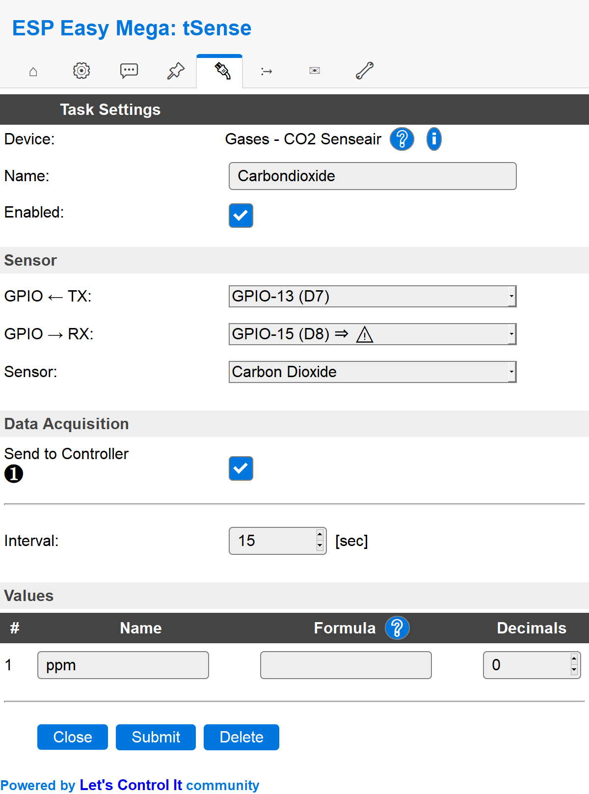
Task settings
Device: Name of plugin
Name: Name of the task (example name CO2)
Enable: Should the task be enabled or not
Sensor
GPIO <– TX: TX is generally set to GPIO 13 (D7).
GPIO –> RX: RX is generally set to GPIO 15 (D8).
Sensor: In this example we use the carbon dioxide sensor.
Note
TX GPIO 1 (D10) and RX GPIO 3 (D9) is hardware serial and have been reported to work better for some users over time compared to the bit-banging (soft) serial used over GPIO 13 and 15.
Data acquisition
Send to controller 1..3: Check which controller (if any) you want to publish to. All or no controller can be used.
Interval: How often should the task publish its value (5..15 seconds is normal).
Indicators (recommended settings)
Indicator |
Value Name |
Interval |
Decimals |
Extra information |
|---|---|---|---|---|
Error status |
Error |
15 |
0 |
Used to present errors (if any):
|
Carbon dioxide |
ppm |
15 |
0 |
|
Temperature |
C |
15 |
1 |
|
Humidity |
RH |
15 |
0 |
|
Relay status |
Relay |
1 |
0 |
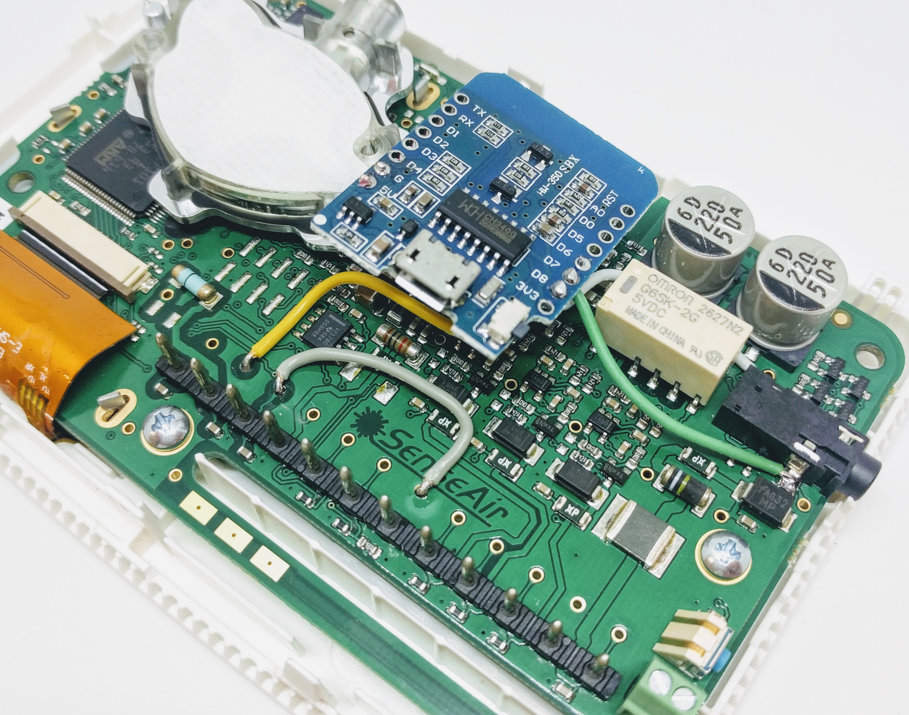
This indicator monitor the software relay status, whereas the yellow/gray wiring monitor the hardware relay status (it’s actual output). Both methods are good, just different. The software way of monitoring the status might be up to 1 second longer (if delay is 1 sec) due to the fact that a switch status is send instant compared to the relay status indicator which is sent once every X seconds. |
Temperature adjustment |
Level |
1 |
0 |
Only available in some versions of the tSense. This raw value goes from 0 - 1000 in 9 steps. To have them displayed as -4 to 4 use this formula:
To have them displayed as 1 to 9 use this formula:
|
ABC period |
N/A |
Note
If you want to use the relative carbon dioxide percentage (2000ppm = 100% and 350ppm = 0%) you should use this
100-(2000-%value%)/(2000-350)*100 as a formula. And instead of ppm as value name you should use
RCO2 (relative CO2) and 1 decimal.
Rules examples
on CO2#Level do
 if [CO2#Level]>2000
   Publish,%sysname%/Alarm,CO2 level is too high!
 endif
endon
Commands available
Command (GPIO/Value) |
Extra information |
|---|---|
Value:
|
Used in tSense (K70) to set the relay to either |
Where to buy
Store |
Link |
|---|---|
Senseair |
$ = affiliate links which will give us some money to keep this project running, thank you for using those.
More pictures
There’s two main ones, the EFA model and the standard model (see different GUI below). The hardware is the same (K70) but different firmware separates them. No one is better then the other, they are just different.
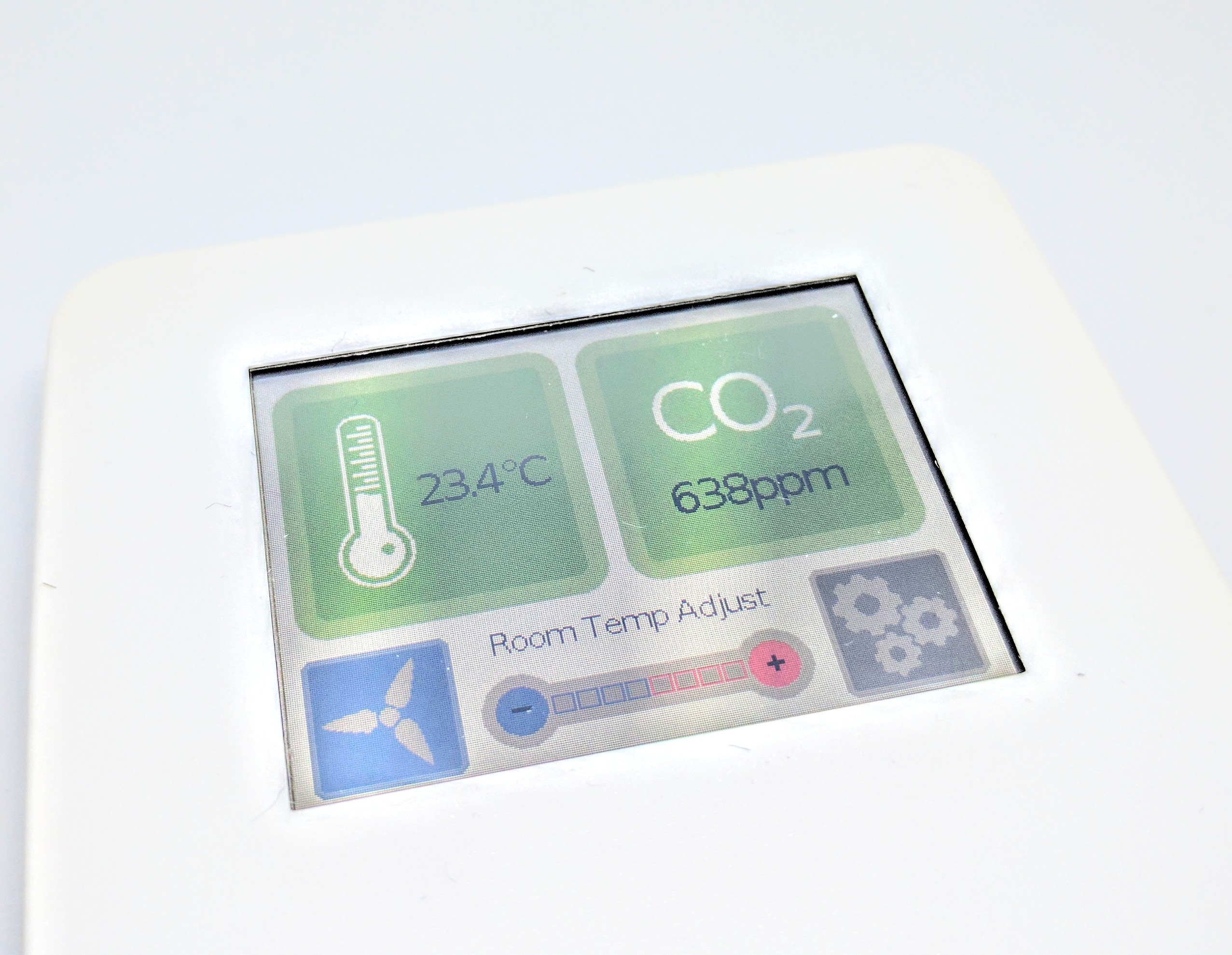
The EFA model of tSense generally displays the temperature and carbon dioxide level. Other than that you have a software button for controlling the internal relay (on and off). It even have a 9 step slider used to control the indoor temperature (monitoring the status of this slider is possible using the plugin).
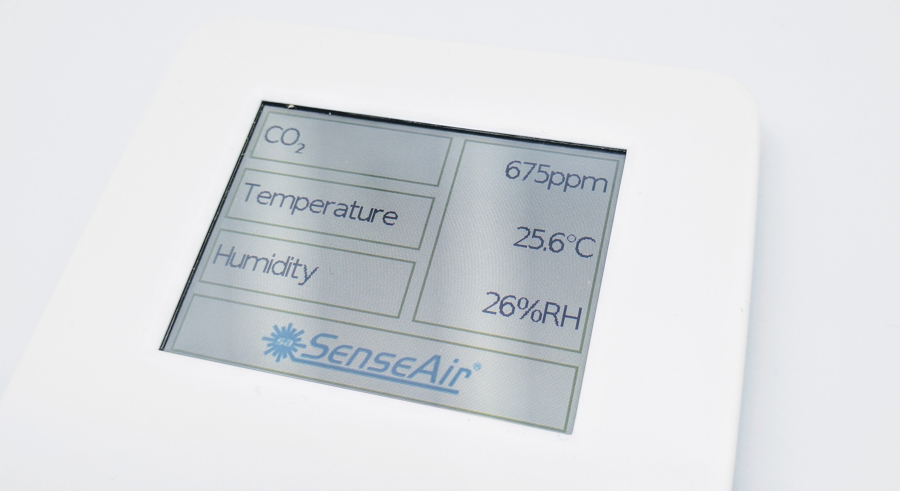
The standard model of tSense display temperature, humidity and carbon dioxide level on the main page. The relay can only be set to trigger by the settings menu where you can have a target level where the relay will activate.
Mounting the D1 mini inside enclosure
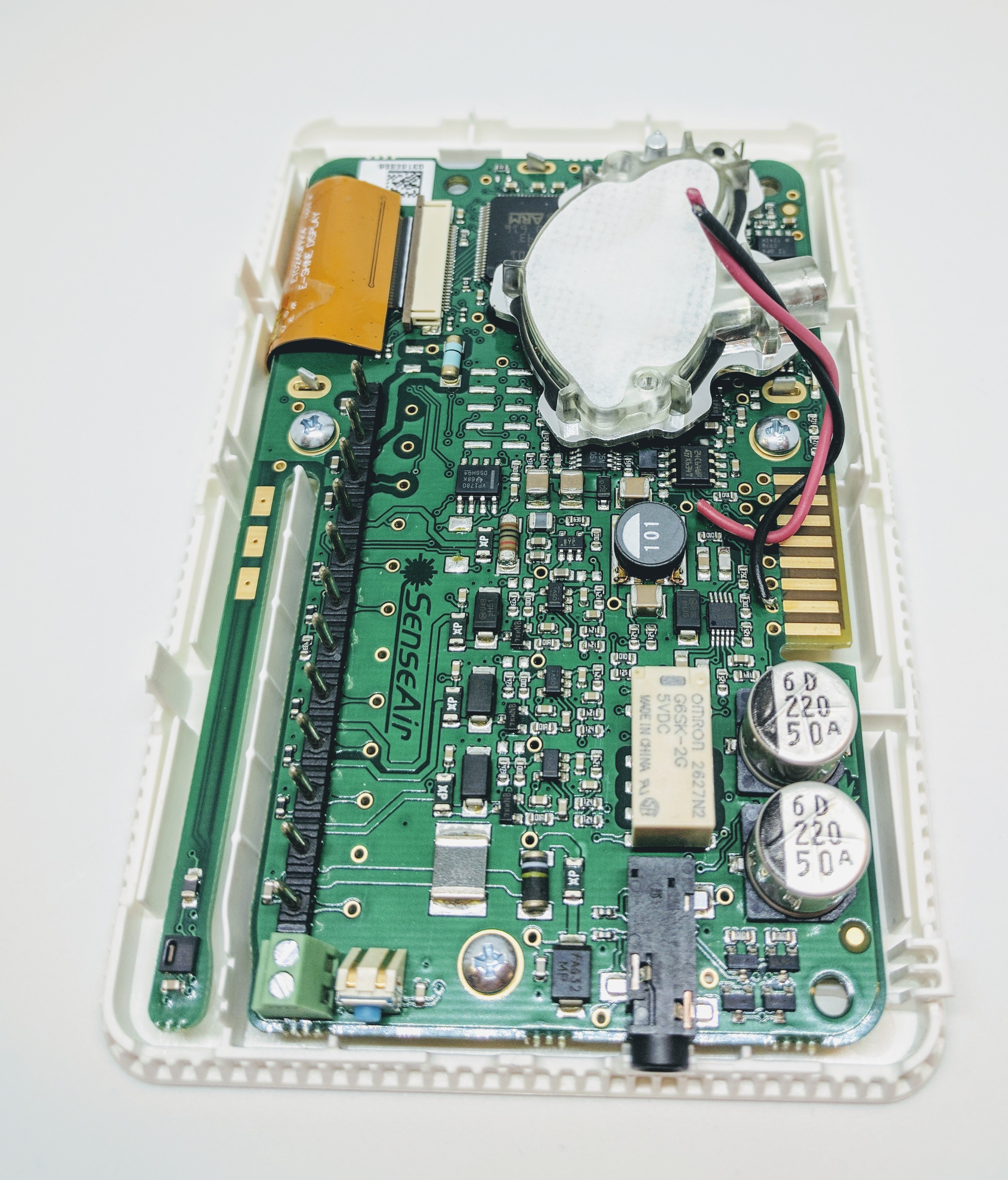
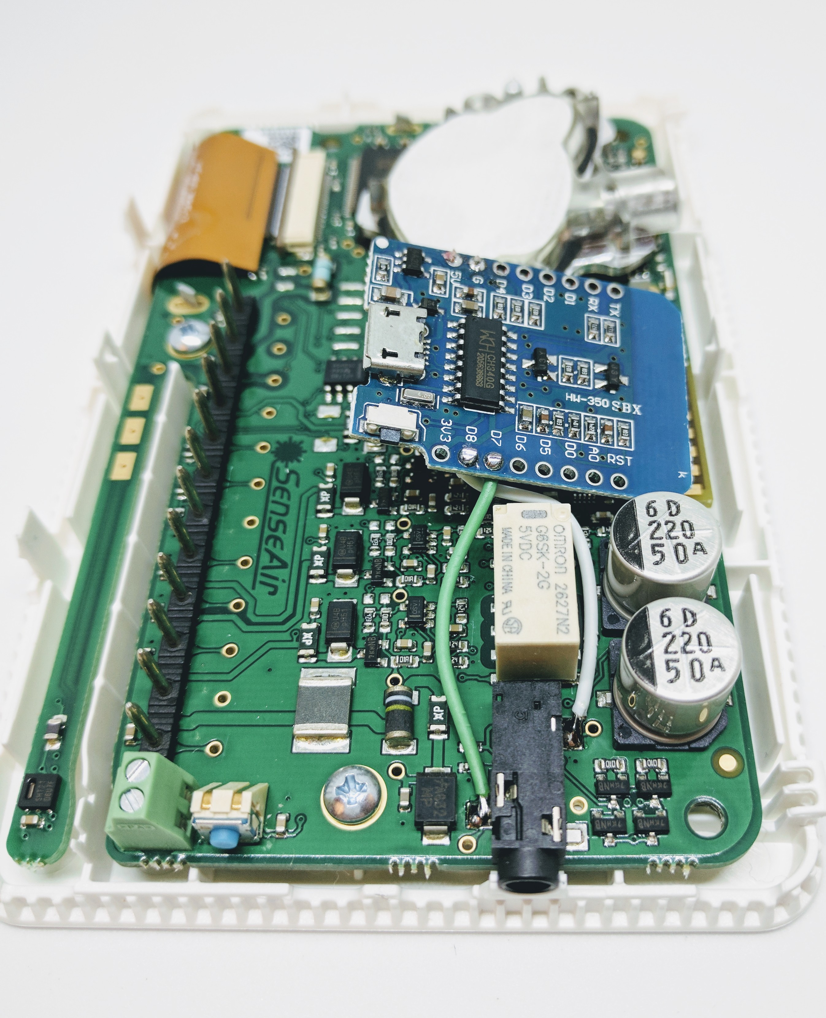
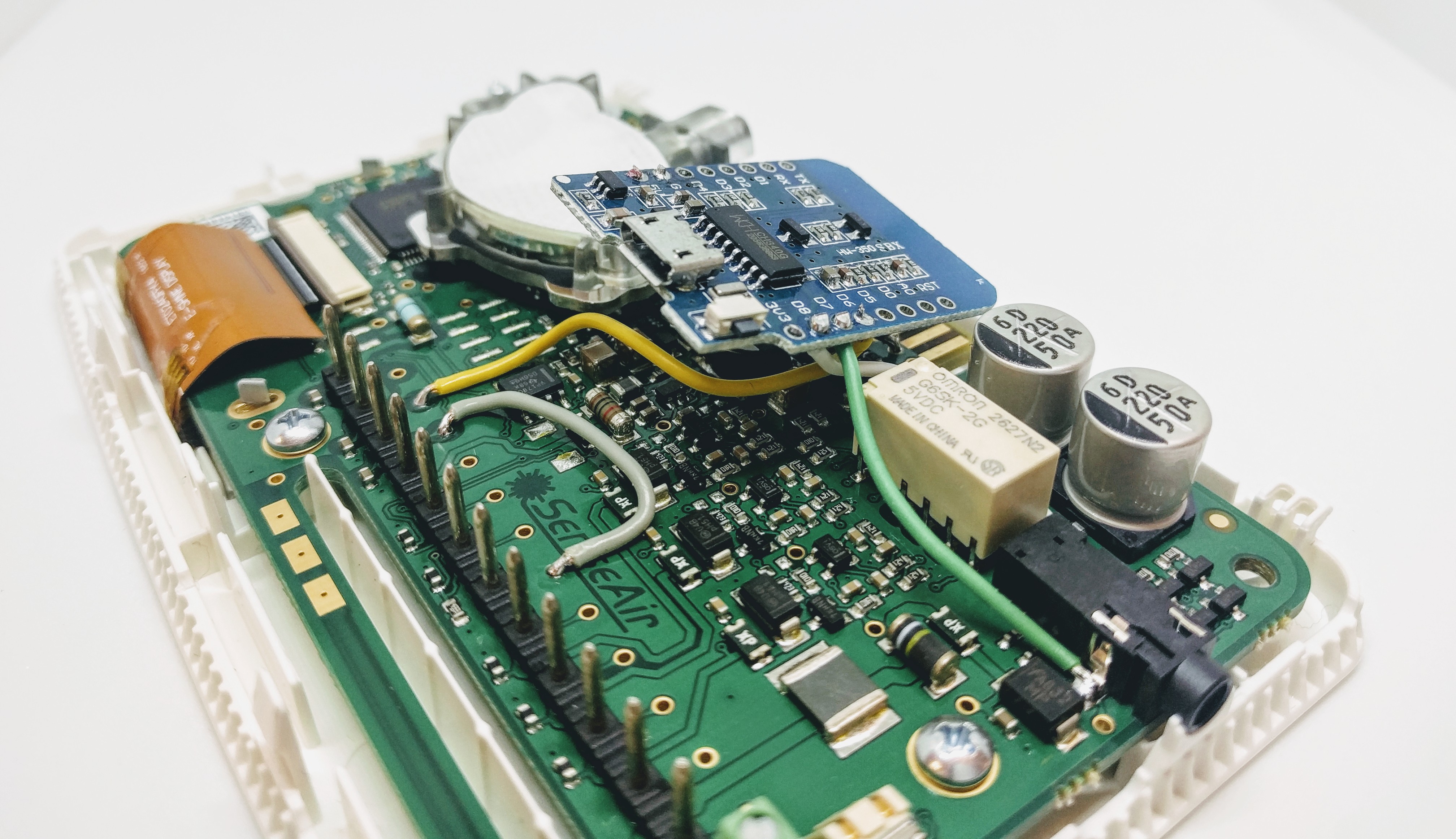
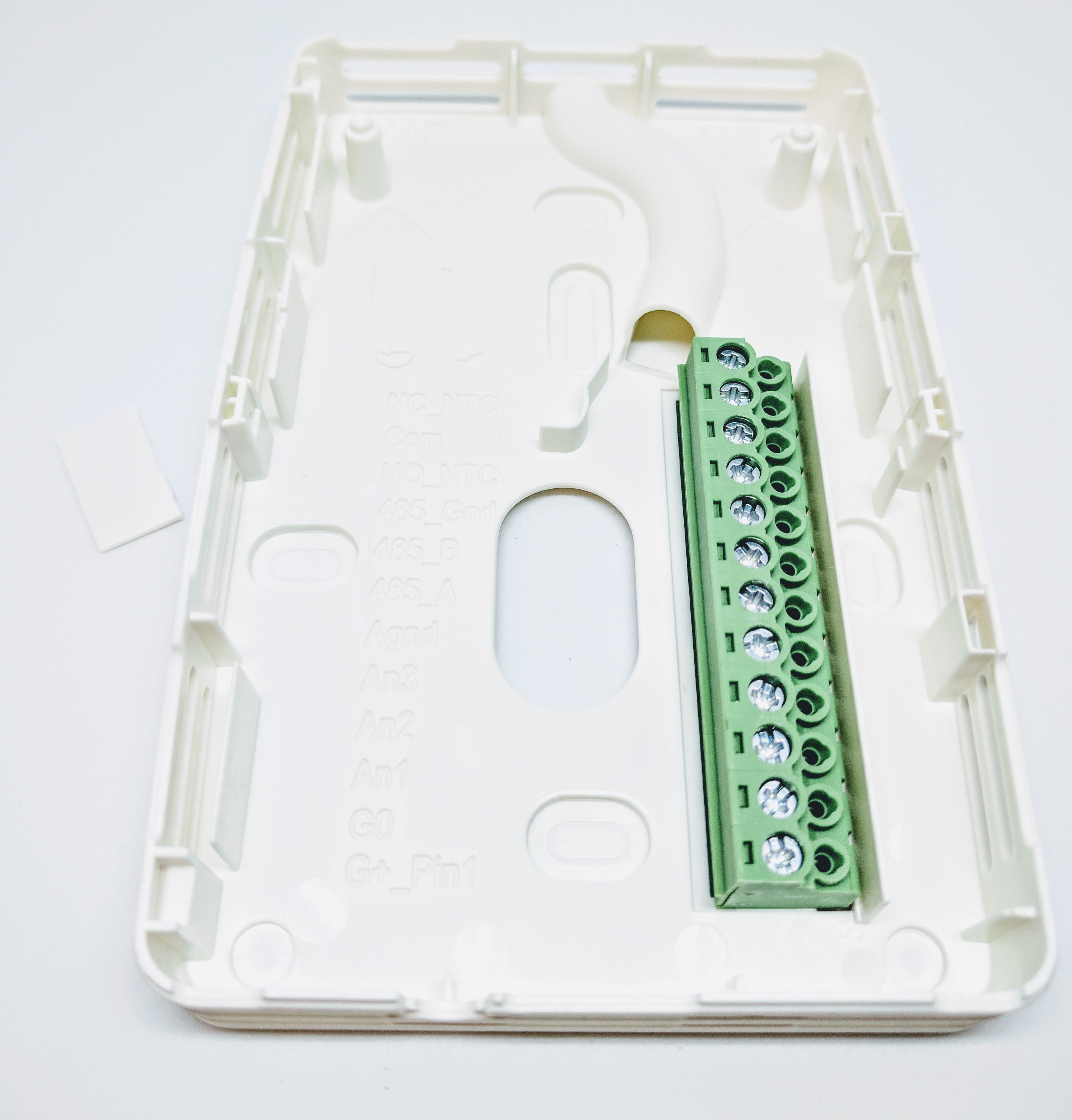
When you first open up the housing you find this:
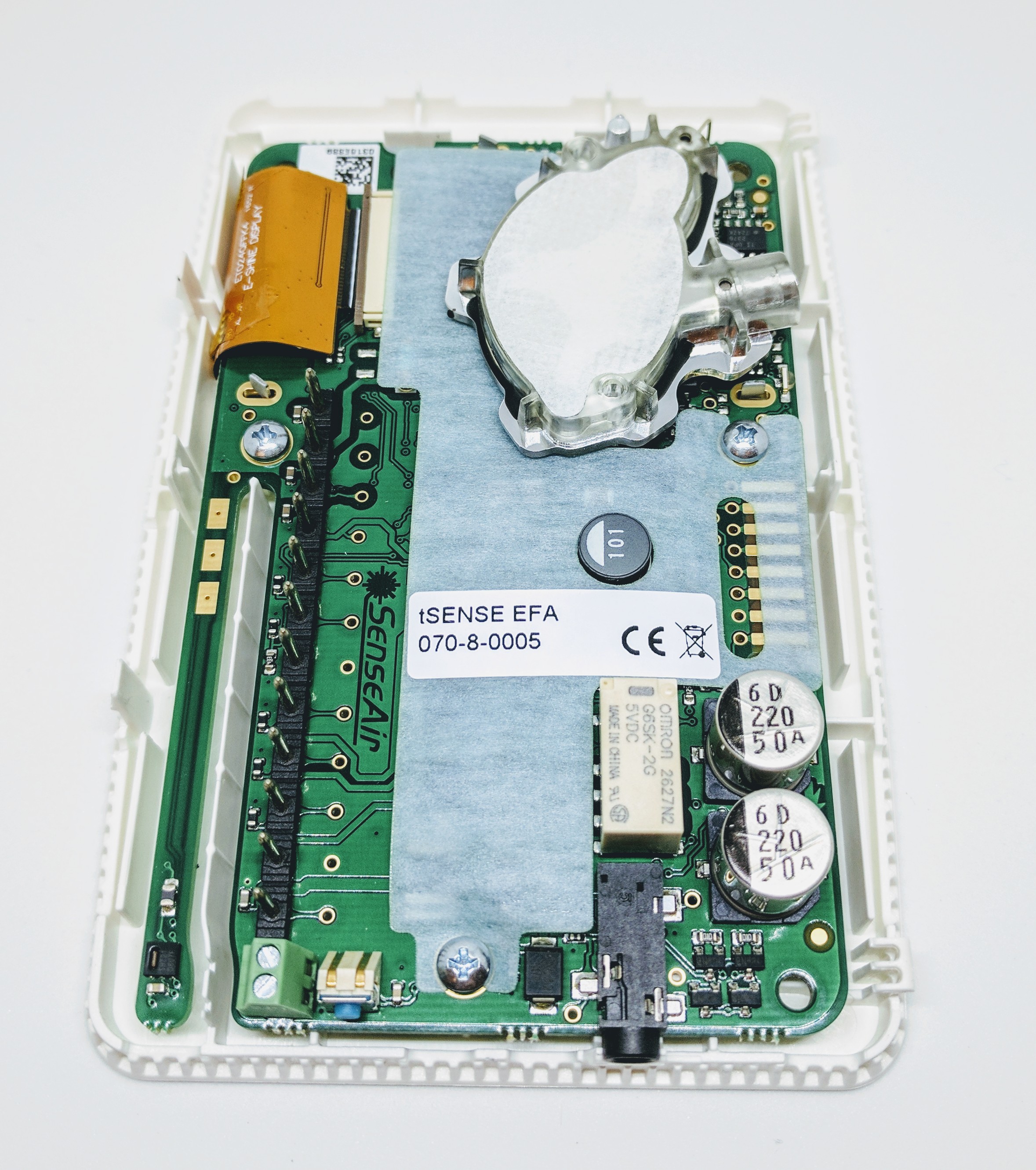
Remove the plastic cover to expose the pcb-board:
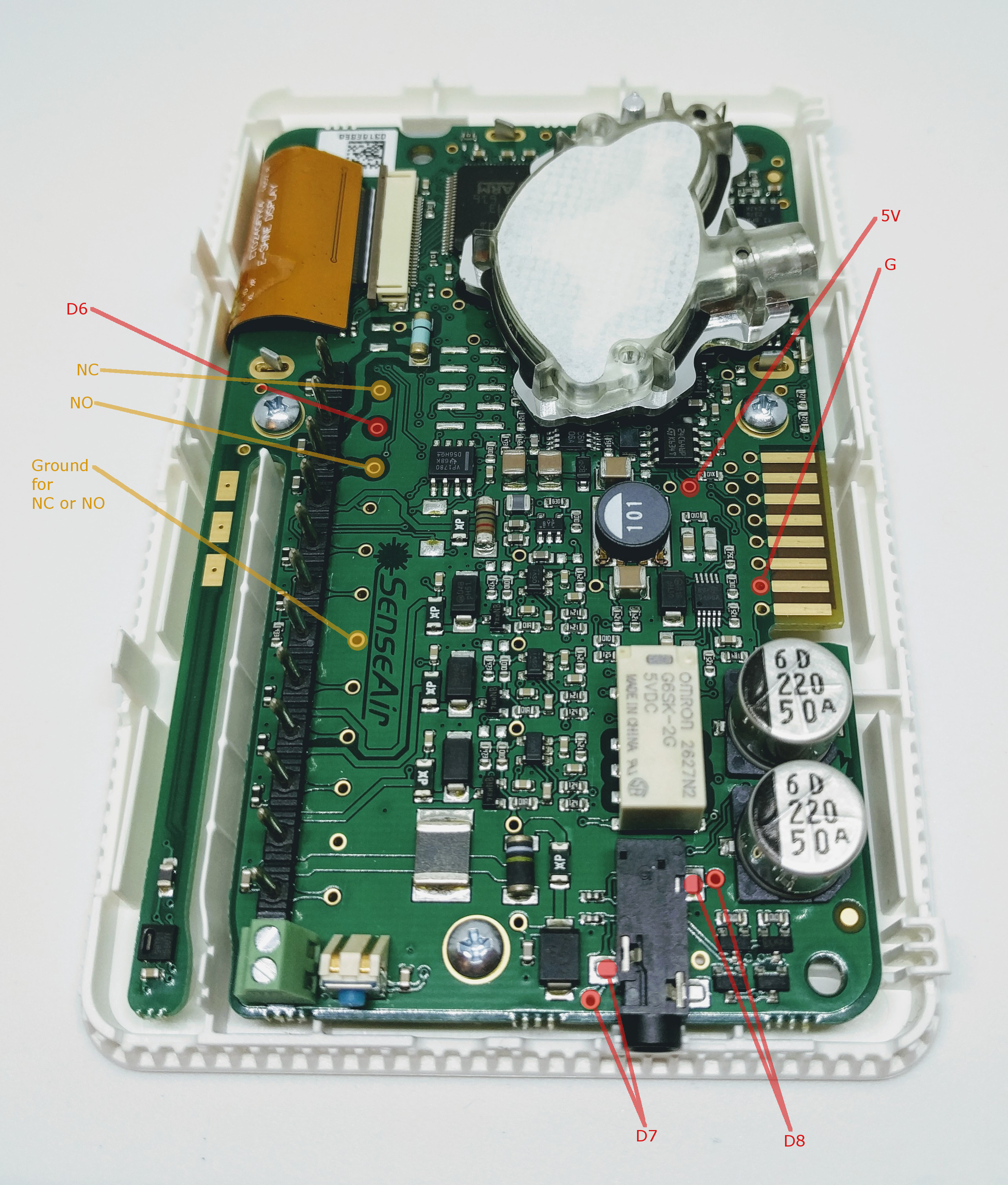
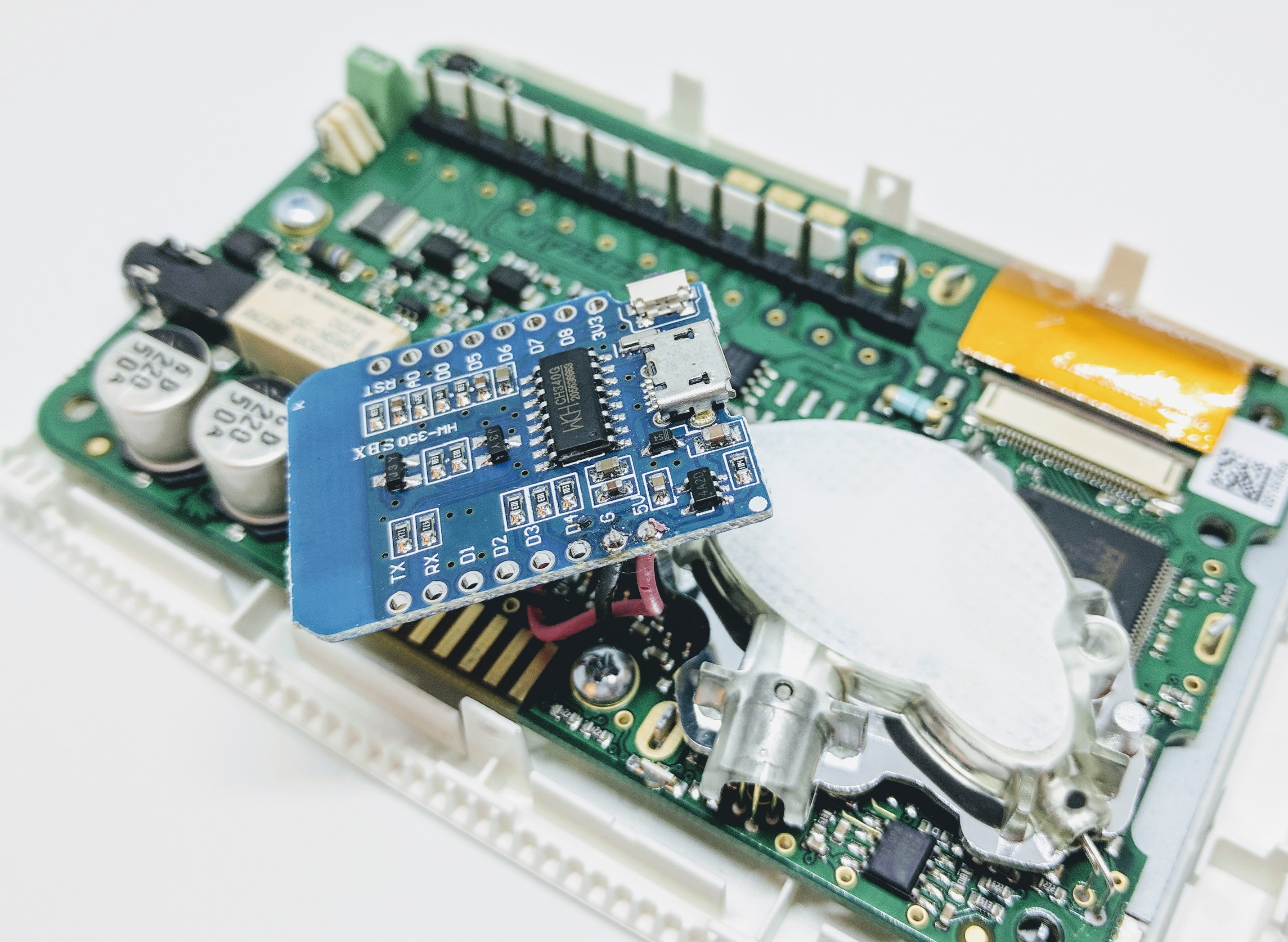
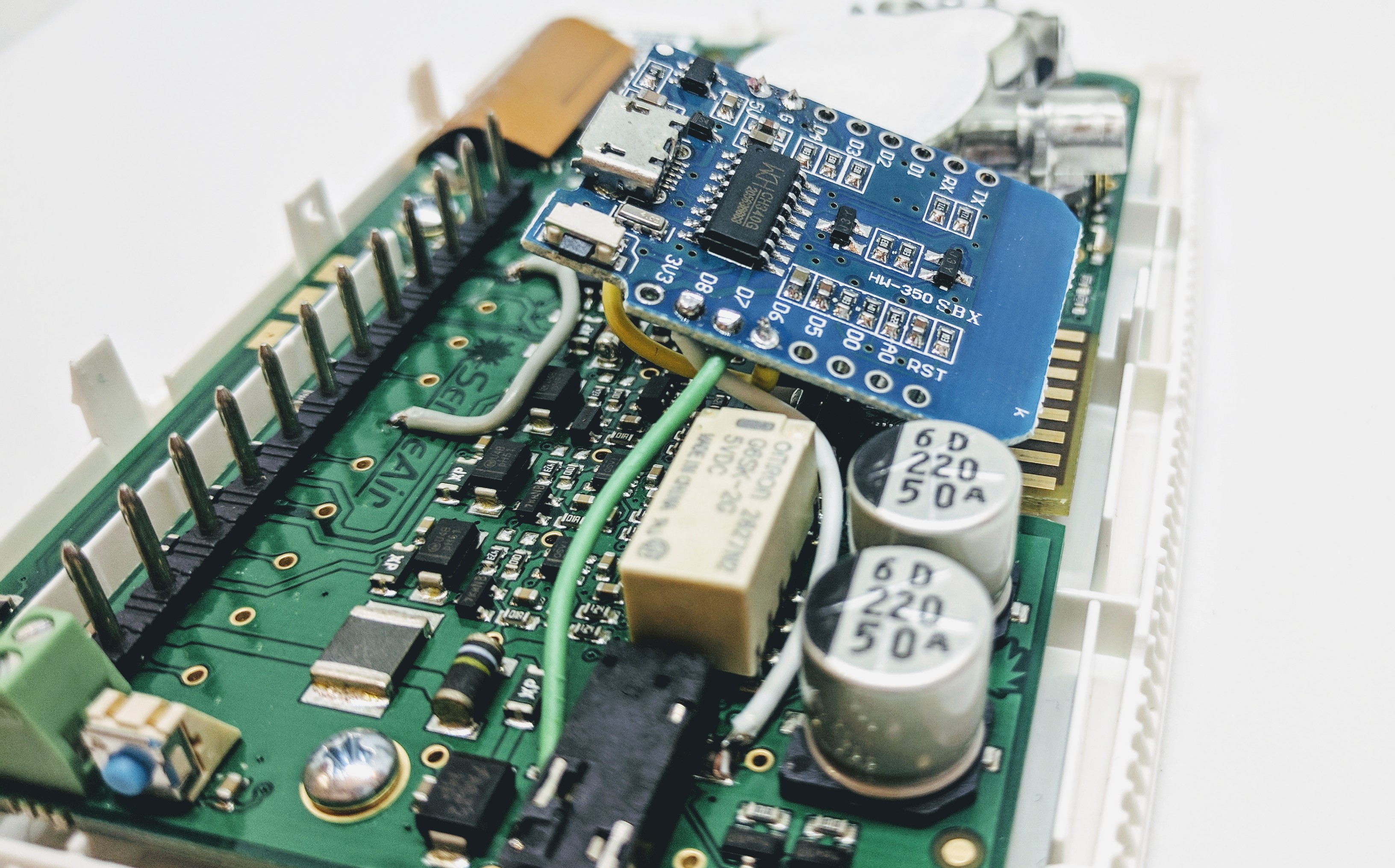
To get power and ground to the ESP we hi-jack these vias:
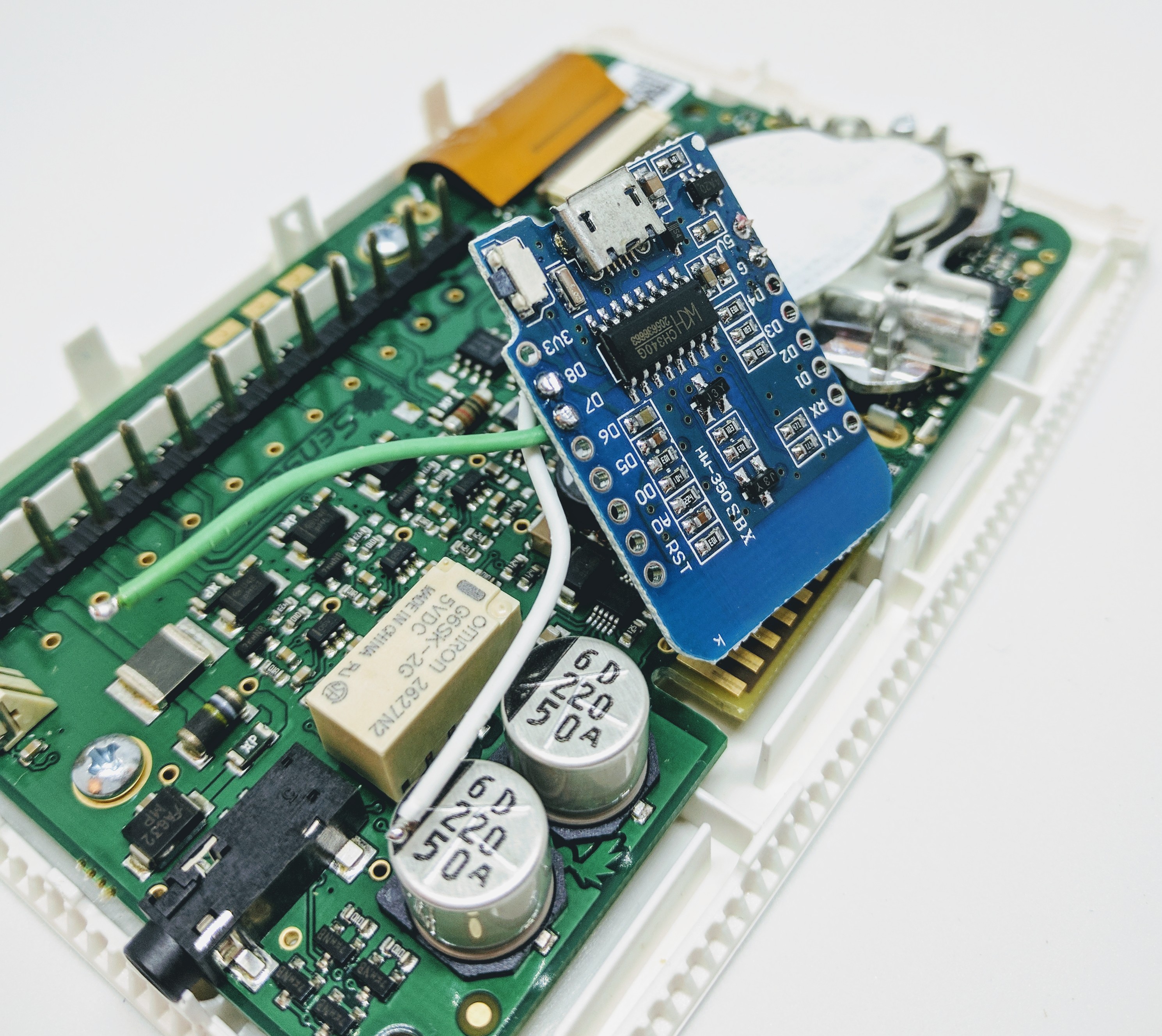
Connect these to the ESPs 5V and G:
The ESP monitor the tSense through the serial ports, green to D7 (GPIO-13) and white to D8 (GPIO-15):
Use the 3.5mm pads or the vias on the tSense:
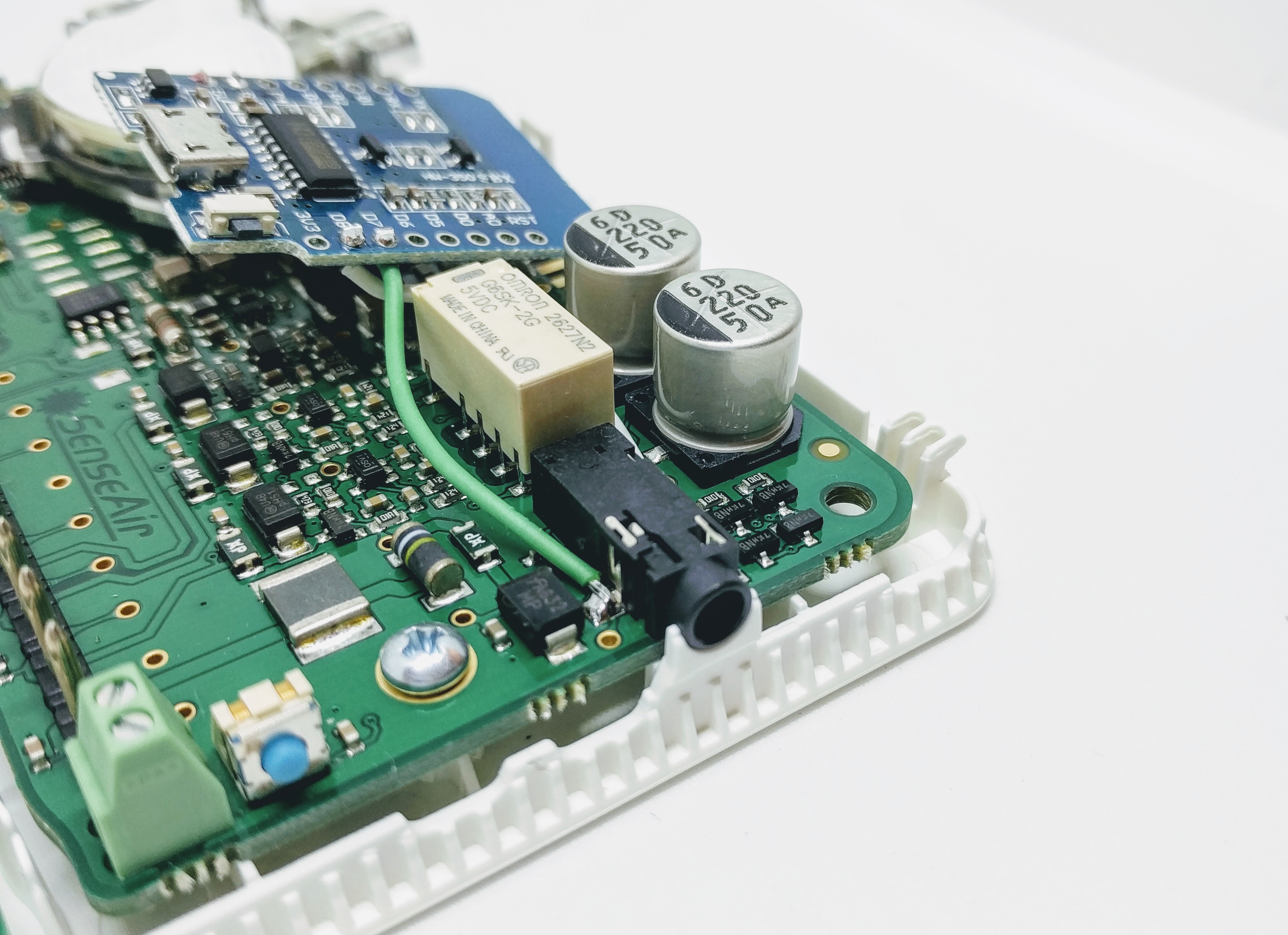
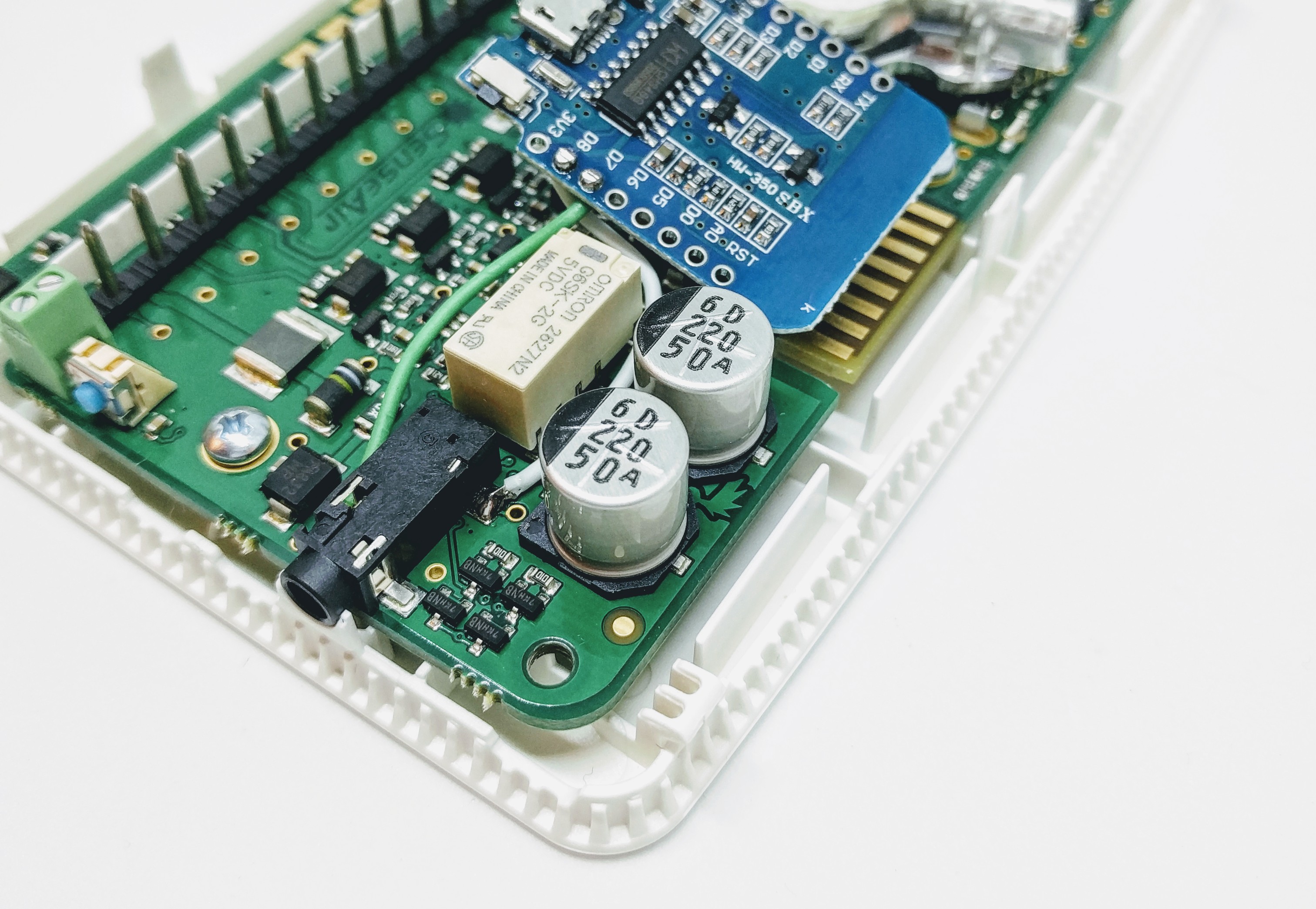
Monitoring the relay (hard wired)
Note
Please observe that you cannot CONTROL the relay using this method, only monitor its status.
To control the relay you need the latest plugin and use senseair_setrelay command.
To fixate the ESP board you could use a tape pad with double sided adhesive:
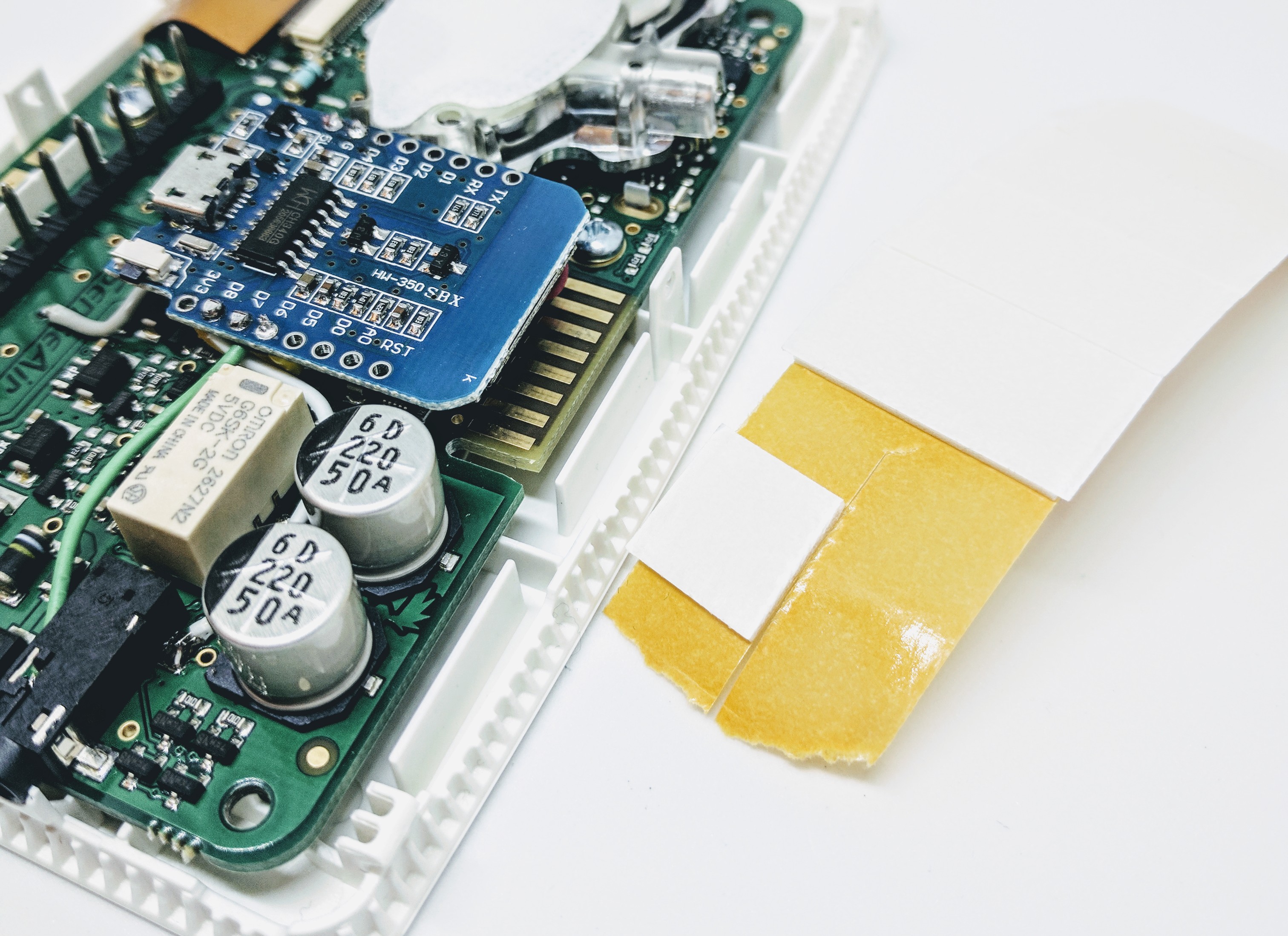
Before re-positioning the unit onto the back panel you need to remove a plastic wall (just bend it and it will break):
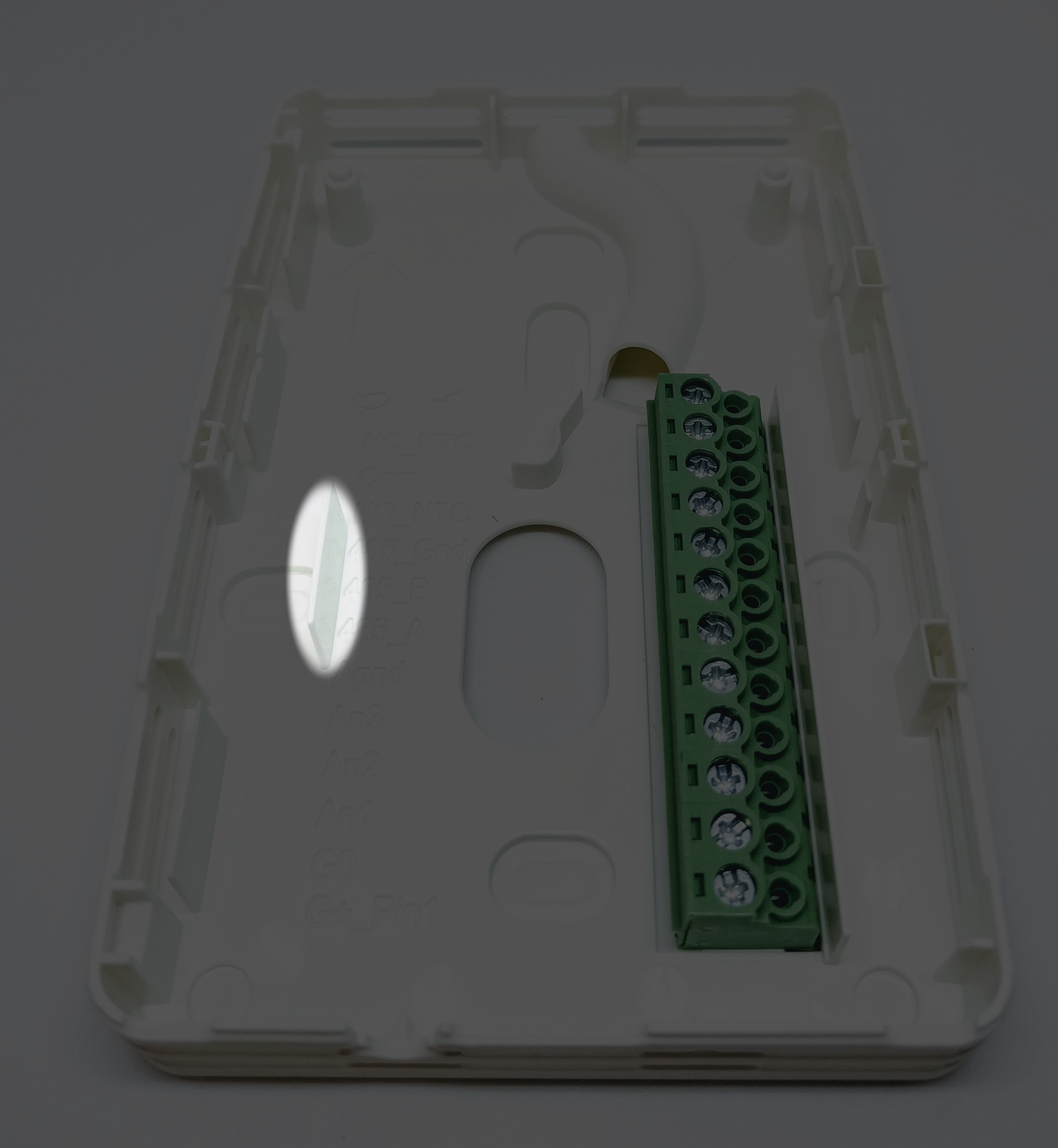
DONE! Power up using the tSense’s 24VDC/24VAC (the unit is possible to function with input power 9VDC - 24VDC with no problem) power adaptor.