Keypad - PCF8574 / MCP23017 / PCA8575
.
Plugin details
Type: Keypad
Name: PCF8574 / MCP23017 / PCA8575
Status ESP32: COLLECTION
Status ESP8266: COLLECTION
GitHub: P061_KeyPad.ino
Maintainer: .
Used libraries: .
Supported hardware
.
This plugin is used to get input from buttons/keys or a keypad transformed to a ScanCode, that can be handled in rules. The keys are connected directly or in a matrix to an 8 or 16 port I2C I/O chip. Currently supported chips are PCA8574/PCA8574A (8 I/O ports), MCP23017 and PCA8575 (16 I/O ports). Depending on the configuration, this allows to connect up to 72 keys to a single I/O chip (9*8 matrix). The PCA8575 chip doesn’t have internal pull-up resistors, so these must be added externally.
Direct chip mode means that each I/O port is connected to a key, and connects to GND when pressed.
Matrix chip mode means that a matrix is created with half of the I/O ports as row and the other half as columns. At every crossing of the matrix, a key can be connected, connecting the row and column wires when pressed. The extra, 9th, row is formed by GND.
The plugin generates a ScanCode, depending on either the button-order in ‘direct’ mode, or the row/column position in the ‘matrix’ mode.
When pressing multiple keys at the same time, the lowest ScanCode value is returned, any other key(s) are ignored.
From the source-code:
Connecting KeyPad matrix to MCP23017 / PCF8575 chip:
row 0 = GND   (optional if 9 rows needed)
row 1 = GPA0 / P00
row 2 = GPA1 / P01
...
row 8 = GPA7 / P07

column 1 = GPB0 / P10
column 2 = GPB1 / P11
...
column 8 = GPB7 / P17

Typical Key Pad:
     C1  C2  C3
R1   [1] [2] [3]
R2   [4] [5] [6]
R3   [7] [8] [9]
R4   [*] [0] [#]

Connecting KeyPad matrix to PCF8574 chip:
row 0 = GND   (optional if 5 rows needed)
row 1 = P0
row 2 = P1
row 3 = P2
row 4 = P3

column 1 = P4
column 2 = P5
column 3 = P6
column 4 = P7

Connecting KeyPad direct to PCF8574 / MCP23017 / PCF8575 chip:
common = GND
key 1 = P0 / GPA0 / P00
key 2 = P1 / GPA1 / P01
...
key 8 = P7 / GPA7 / P07
For 16 bit I/O expanders
key 9 = -- / GPB0 / P10
key 10 = -- / GPB1 / P11
...
key 16 = -- / GPB7 / P17
NB: PCF8575 needs pull-up resistors on all 16 ports to work as intended, as the chip doesn't have internal pull-ups
Often used matrix keypads, in 16 and 12 key configuration:
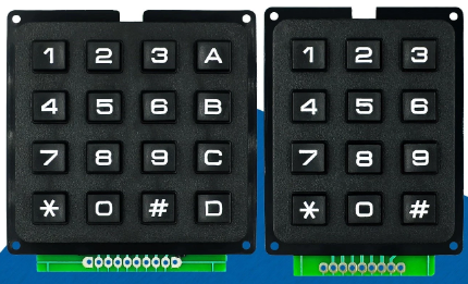
(Image sourced from Aliexpress)
Note
Due to technical reasons, the MCP23017 rev. D chip no longer has (official) Input capability on the GPA7 and GPB7 pins!
Following this news article, the MCP23017 I2C chip, since revision D released around 2022, might possibly no longer accept signals reliably for Input on the GPA7 and GPB7 pins. Other sources (links no longer available) suggest these pins have had issues taking input signals since at least 2014, so your milage may vary! (Output is still working as usual on these pins.)
This may have impact on the use of this board/chip with this plugin when using a MCP23017 rev. D.
Possible alternatives are using an older revision of this chip, or switching to a different chip, like PCF8574 (8 I/O pins), PCF8575 (16 I/O pins, external pull-up), 74HC165 (Input only), 74HC595 (Output only).
Configuration
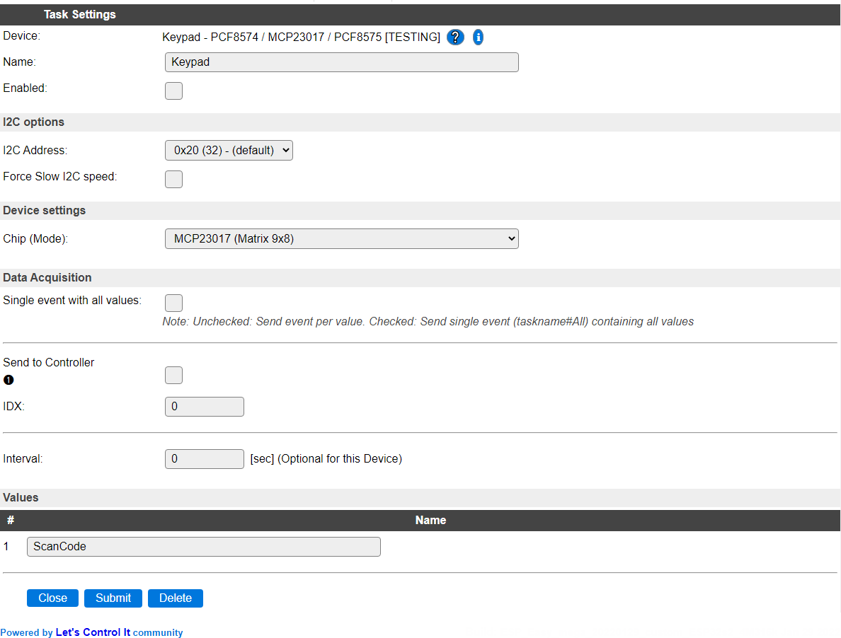
Name A unique name should be entered here.
Enabled The device can be disabled or enabled. When not enabled the device should not use any resources.
I2C Options
The available settings here depend on the build used. At least the Force Slow I2C speed option is available, but selections for the I2C Multiplexer can also be shown. For details see the I2C Bus page
I2C Address: The address the device is using. Usually, for this type of I/O boards, the I2C address can be configured by connecting A0/A1/A2 to either GND or VCC.
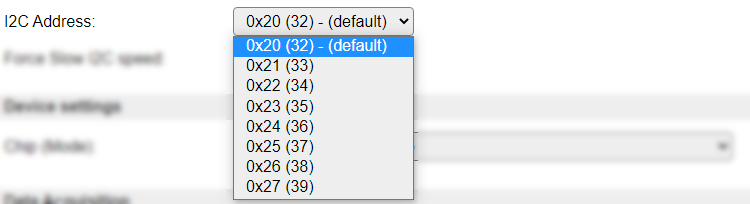
Depending on the chip used, different sets of I2C addresses are available to select from.
For MCP23017 and PCA8575, these are the available addresses:
For PCA8574 and PCA8574A, these are the available addresses:
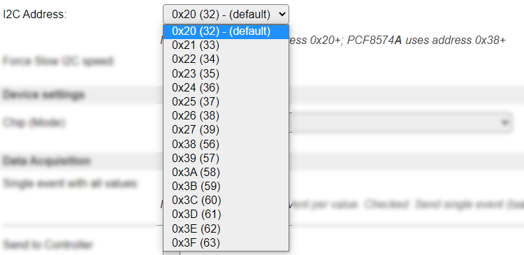
If a Chip (Mode) for PCA8574 is selected, an extra message is shown, as the A version of that chip uses a different address-range:

Device Settings
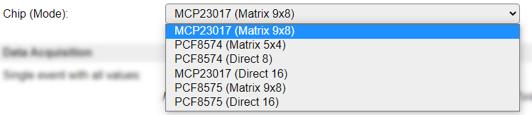
Chip (Mode): Select the configuration needed.
Available options:
Data Acquisition
This group of settings are standard available configuration items.
Single event with all values: When this setting is enabled, all available values will be sent in a single event
<TaskName>#All, with all values in order as arguments to the event.Show derived values: When checked, the Devices overview page, and the
/jsonendpoint (used for updating the Devices overview page) will include any Derived values as defined. See theTaskValueSetDerivedandTaskValueSetPresentationcommands.Event & Log derived values: When checked, the Derived values will be generated as Events, to be handled in Rules, and sent to logging devices like the Syslog server and/or SD-card logging.
(The derived values options are only available if String variables feature is included in the build.)
Send to Controller: Select the Controller(s) to send the Values to, either on a
TaskRuncommand applied to the task, or on an Interval time action.
Send to Controller is only visible when one or more Controllers are configured.
Depending on the controller capabilities, some configuration settings may be shown:

All configured Controllers are shown here, including the enabled or disabled state (multiple Controllers can be enabled, only a single MQTT Controller can be enabled at one time!).
For each controller the user can select wether the data should be sent on each Interval (or explicit TaskRun).
For the Domoticz controllers the value index (IDX) has to be configured.
For some controllers, like Home Assistant/openHAB, there are extra options available.
Group: This represents the group id to combine all values from multiple tasks into a single grouped-device during MQTT AutoDiscovery. Groups, by design, can span multiple ESPEasy devices, if desired, as long as the Task/Valuename combinations are unique. If a group should only combine Tasks from a single ESPEasy unit, the group id should be unique across multiple ESPEasy units. The group description, default Group <n>, can be adjusted in Home Assistant. If the Group value matches the current Unit nr, the Unit name,
%sysname%, is used instead of Group <nr>.Retained: For MQTT Controllers, this setting can be enabled to send the values for the current task with the Retain flag set. The Publish Retain flag in the Controller settings will override this by sending all task values with Retain flag enabled.
Send derived: This checkbox determines if any configured Derived values should also be sent to the controller (and included in the AutoDiscovery if that’s available and enabled).
Resend MQTT Discovery: When checked, will start a resend of the MQTT Discovery process for this task after a random delay, when Submit is clicked, so any changed settings will be updated in the MQTT broker. This setting is only available if the controller is enabled, the Auto Discovery feature is available and enabled for the controller. This setting is not stored.
Other controllers, like f.e. FHEM HTTP, do not support additional settings besides the checkbox to enable sending the data.
Interval By default, Interval will be set to 0 sec.
Values
The key scan code is available in ScanCode. After releasing the key, the ScanCode is reset to 0.
Change log
Changed in version 2.0: …
added 2022-01-23 Add support for PCA8575 chip, and multi-instance use of the plugin.
added Major overhaul for 2.0 release.
Added in version 1.0: …
added Initial release version.