Generic - I2C Generic
User-configurable generic I2C protocol plugin
Plugin details
Type: Generic
Name: I2C Generic
Status ESP32: COLLECTION CLIMATE DISPLAY ENERGY NEOPIXEL
Status ESP8266: NEOPIXEL
GitHub: P180_I2C_generic.ino
Maintainer: tonhuisman
Used libraries: .
Description
This plugin offers generic access to I2C devices, by providing a set of commands for reading and writing to an I2C address, manipulating an Enable and Reset GPIO pin, inserting a delay, conditionally stop executing the commands, calculating with the data read from the device, and assigning (intermediate) results to Values 1..4.
This enables the implementation of yet unsupported I2C devices or use I2C devices in builds where the available plugin isn’t included.
Warning
This plugin is in the ‘pro’ category of plugins (i.o.w. not really Easy to use), and requires in-depth studying of the datasheet for the device, extracting the required commands and calculation(s) for implementing correct usage. (Some examples available below)
Example device configurations
Configuration
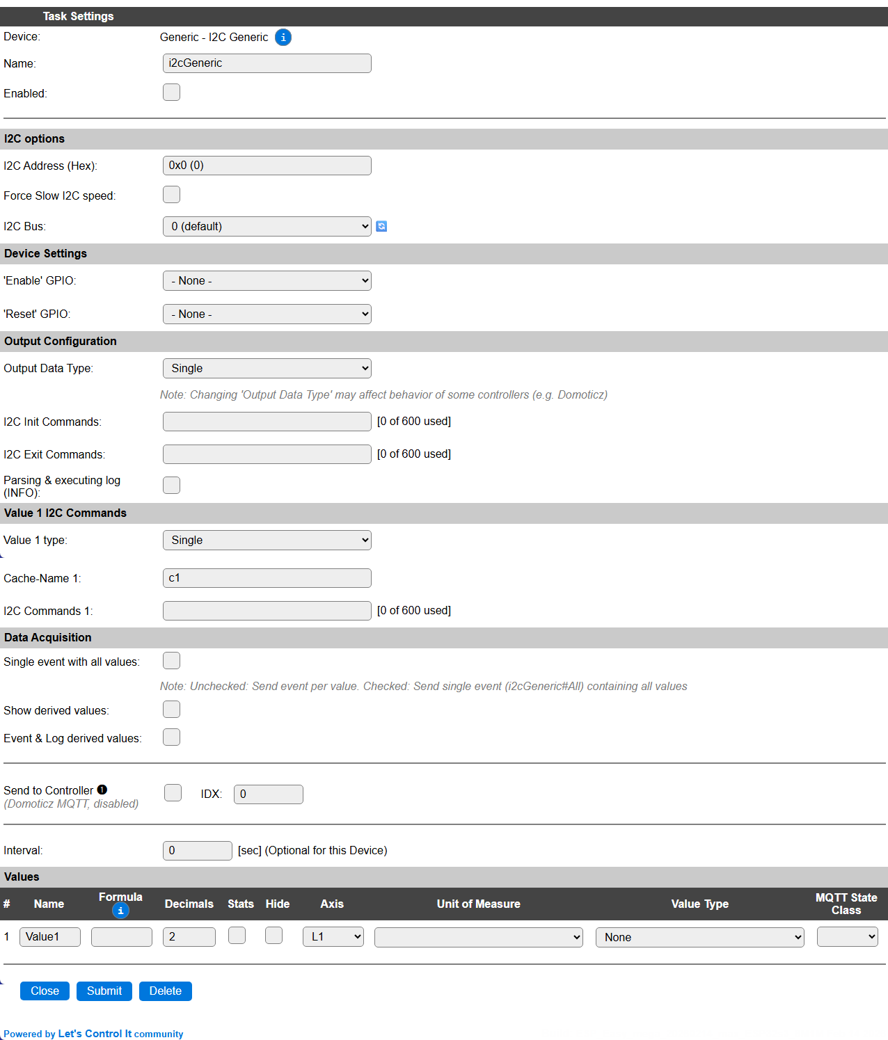
Name: Required by ESPEasy, must be unique among the list of available devices/tasks.
Enabled: The device can be disabled or enabled. When not enabled the device should not use any resources.
I2C options
I2C Address (Hex): Because of the flexible nature of the plugin, setting the I2C address requires typing the hexadecimal I2C address of the device. This should be in the range 0x01 .. 0x7F.
The available I2C settings here depend on the build used. At least the Force Slow I2C speed option is available. This plugin can also be used with an I2C Multiplexer, or use a separate I2C Bus when configured, to allow for multiple sensors on a single ESP. For details see the I2C Bus page.
Device Settings
‘Enable’ GPIO: Some devices have an Enable pin, that allows the device to be disabled, f.e. to conserve power, or extend the usable lifespan of the device. This can be set by an I2C command (see below).
‘Reset’ GPIO: Some devices require to be reset, either after power-on, during use, or when not operating properly. This can be controlled by an I2C command (see below).
Output Configuration
Output Data Type: This setting determines the number of available Values, and is also used by f.e. the Domoticz controllers for sending data in the correct format. F.e. when configuring a Temperature & Humidity sensor, it makes sense to choose Temp / Hum here.
I2C Init Commands: A sequence of commands, documented in detail below, that will be used to manipulate the sensor when the plugin is enabled. This can f.e. be used to initialize the sensor, set the ‘Enable’ GPIO in the Enabled state, or pulse the ‘Reset’ GPIO to reset the device. The last value is used as the initialization result value, where 0 is
falseand <> 0 istrue. Often this sequence needs;calc.1appended, to return atrueresult.I2C Exit Commands: A sequence of commands that will be sent to the device when the plugin is disabled. This can f.e. be used to set the ‘Enable’ GPIO in Disabled state, or set the device in a power-down state.
Parsing & executing log (INFO): When enabled, the command sequences will be logged during parsing and execution at INFO level, that’s often very helpful when configuring & testing a new I2C device. Should best be disabled for production use to avoid excessive logging output.
Value x I2C Commands
For each Value1 .. Value4 output, depending on the Output Data Type setting, a group of settings is available:
Value x type: Here you can select a specific output type for each Value. This shows a selection of the Output Data Type selector, but only the single-value types. This will also be used for sending to Domoticz controllers and for MQTT Auto-Discovery.
Cache-Name x: Should be set to a unique name (for this task), so the parsed & pre-processed command sequence will be stored in a memory-cache, to significantly improve the speed of the plugin in runtime. Initially the Cache-name is set to
c1..c4(depending on the number of values selected) and can be changed as desired. When empty it will be reset tocXagain.I2C Commands x: The sequence of commands to execute for this value. Nothing will be done if this is empty. The corresponding Value output can be set from another I2C Commands sequence. The currently used vs. the available space is shown next to the field. I2C Commands are explained below.
Data Acquisition
This group of settings, Single event with all values and Send to Controller settings are standard available configuration items. Send to Controller is only visible when one or more Controllers are configured.
Interval Interval is optional, and will be set to 0 sec. by default. The data will be collected and optionally sent to any configured controllers using this interval.
Values
The plugin provides 1 .. 4 Values. The names can be set as desired. A formula can be set to recalculate, f.e. when a temperature has to be presented in ° Fahrenheit instead of ° Celcius: %c_c2f%(%value%). The number of decimals can be set as desired.
In selected builds, per Value Stats options are available, that when enabled, will gather the measured data and present most recent data in a graph, as described here: Task Value Statistics:
Plugin Commands available
Command |
Extra information |
|---|---|
|
This command will often be used in Rules, as re-typing a command sequence can be quite tedious. In that case, when To be able to use the value retrieved from the I2C device, the The |
|
This command is used to execute a cached I2C Command sequence, and optionally store the result in a task value. |
0 - Disable plugin logging 1 - Enable plugin logging |
Enable or disable logging for the I2C Command sequence(s) during parsing and execution. NB: No logging will be generated during parsing or execution of 1/sec, 10/sec or 50/sec event processing to avoid overloading the ESP, as logging can incur quite a processing penalty. |
Get Config Values
Config value |
Information |
|---|---|
|
Returns the logging state (0/1). |
|
Returns the value remaining after executing the I2C commands. Should not use the
|
I2C Commands
I2C Commands (sequences) are available for reading and writing the device on the selected I2C Bus, using the configured I2C address. If the address is not set, the plugin won’t start.
The general I2C Command format is: <command>[.<dataformat>[.<length>]][.<arguments>....];...[|(1ps|10ps|50ps)|<command_sequences>]
The command separator is a semicolon
;The argument separator is a period
.The event separator is a pipe-symbol
|
For dataformat there are a limited set of options available:
u8: uint8_t (1 byte)u16: uint16_t (2 bytes)u24: uint24_t (3 bytes)u32: uint32_t (4 bytes)u16le: uint16_t (2 bytes, little endian)u24le: uint24_t (3 bytes, little endian)u32le: uint32_t (4 bytes, little endian)8: int8_t (1 byte, signed)16: int16_t (2 bytes, signed)24: int24_t (3 bytes, signed)32: int32_t (4 bytes, signed)16le: int16_t (2 bytes, signed, little endian)24le: int24_t (3 bytes, signed, little endian)32le: int32_t (4 bytes, signed, little endian)b[.<length>]: <length> uint8_t (bytes), <length> is needed for reading onlyw[.<length>]: <length> uint16_t (words), <length> is needed for reading onlystr[.<length>]: <length> String, <length> is needed for reading only (not avaiable on ESP8266 builds by default for code-size reasons)
The commands available can either be used with the full command, or the 1 character shortcut to save some space in the limited available storage:
get.<format>[.<len>]:(g): Read the number of bytes matching the format from the device.<len>can be a calculation, f.e. to use%value%from a previous command.put.<format>.<data>[.<data>...]:(p): Write data to the device, in the format specified. Forborwthe provided data and format determines the length of the data to send.datacan be from a global variable, expanded just before execution.read.<format>[.<len>].<reg>:(r): Read data in the requested format from a register in the device.<len>can be a calculation, f.e. to use%value%from a previous command.regcan be from a global variable, expanded just before execution.write.<format>.<reg>.<data>[.<data>...]:(w): Write data to a register in the device in the specified format.regand/ordatacan be from a global variable, expanded just before execution. (not applicable forbandwformat!)eval:(e): Evaluate the previous command, and set as selected data forcalcorifcommands.value.<valueIndex>:(v): (1..4 or a value name) Store the last calculated result, or last read value, in the specified Value field.calc.<calculation>:(c): Calculate a result, like Rules, extra available vars:%value%,%pvalue%,%h%,%b0%..%b<n>%,%bx0%..%bx<n>%,%w0%..%w<n>%,%wx0%..%wx<n>%if.<calculation>[.<skip>]:(i): Similar tocalccommand, when the calculation-result is 0 execution is cancelled, or<skip>commands are skipped (forward only) to act somewhat similar to anelseclause.delay.<msec>:(d): (range: 0..500, 0..10 for 1/sec, 10/sec, 50/sec events) Some devices, f.e. after starting a measurement, require some time to process data. This can be handled by a delay. If the delay is <= 10 msec, it will be handled immediately, longer delays are processed asynchronous to avoid blocking the ESP for too long.enable.<state>:(a): (0 or 1) Set the configured ‘Enable’ GPIO pin to the provided state. If the pin is not configured, this command is ignored, and processing continues.reset.<state>.<msec>:(z): (state = 0 or 1, msec = range: 0..500) Pulse the configured ‘Reset’ GPIO pin for the provided time (msec) to the state requested, to reset the device. If the pin is not configured, this command is ignored, and processing continues.let.<variable>.<calculation>:(l): Assign the result of a calculation to a global Rules variable. Can use the same plugin variables as available forcalcandif. The resulting variable can also be used from rules, or later in acalc,if,letorletstrI2C command.letstr.<variable>.<calculation>:(m): Assign the result of a calculation to a global Rules String variable. Can use the same plugin variables as available forcalcandif. The resulting variable can also be used from rules, or later in acalc,if,letorletstrI2C command. Only available if String variables are available in the build.
During processing, the data has to be made available to some of the following steps to be able to calculate the outcome. The variables to insert the data are listed here:
%pvalue%: The value currently in the Value field for this command sequence (when run during an Interval or from Rules when a TaskValue index is specified), can be read as ‘previous-value’.
The next variables are only available after an eval I2C Command is executed:
%value%: The value retrieved in decimal presentation, or the read String for formatstr. So if areadorgetcommand was used. Not applicable forb.<length>andw.<length>dataformats, then%h%,%b..%or%w..%variables should be used.%h%: The result of areadorgetformatted as hex bytes with a single ‘0x’ prefix, using the minimal number of digits needed. Forb.<length>orw.<length>dataformat all bytes/words are concatenated. If 7 bytes are retrieved usingget.b.7command,%hwill be replaced by0x00010203040506, or 3 words usingget.w.3with0x000000010002, showing the retrieved data of course.%b<N>%: The value of byte N (0-based!), retrieved using theb.<length>dataformat. This will be a decimal presentation of the data.%bx<N>%: The value of byte N (0-based!), retrieved using theb.<length>dataformat. This will be a 2 digit hexadecimal presentation, without ‘0x’ prefix, of the data.%w<N>%: The value of word N (0-based!), retrieved using thew.<length>dataformat. This will be a decimal presentation of the data.%wx<N>%: The value of word N (0-based!), retrieved using thew.<length>dataformat. This will be a 4 digit hexadecimal presentation, without ‘0x’ prefix, of the data.
For the put and write commands, the data can be from a global variable, in the usual notations, like %10%, %v_bits%, [var#5] etc. When sending an I2C command sequence from rules, the variable shuld be escaped, f.e. \%v_bits\% or \[int#bits\], etc.
Processing commands for 1/sec, 10/sec and 50/sec plugin events
It is sometimes needed to check the state or value of a device more often than the regular Interval setting. For this use-case there is support for the repeating 1/sec, 10/sec and 50/sec events. These events have a short window of time where a few commands can be processed for fetching data or checking the state of the sensor.
To optimize storage space for commands, these events are also stored in the regular I2C Commands settings per value. The prefix for these events are 1ps, 10ps and 50ps, and they are separated from the regular commands by a pipe-symbol |. So a hypothetical configuration that supports a normal read, 1/sec, 10/sec and 50/sec sequence of commands could look like this:
<read_commands>|1ps|<once_a_second_commands>|10ps|<ten_per_second_commands>|50ps|<fifty_per_second_commands>
A few warnings though:
Using 50/sec event I2C commands may slow down the ESP or increase the load, as for processing the commands there are only 20 msec available, and as processing in the plugin is far less efficient than normal C++ code, this should be as short/small as possible, or moved to 10/sec processing (where 100 msec is available) when possible.
Delay commands during these events should be avoided, and will be reduced to max 10 msec duration.
The result from a 1/sec, 10/sec and 50/sec event command sequence is not assigned to the corresponding Value by default, but it can be assigned using the
value.<n>I2C command.If no commands are used for the
<read_commands>sequence, then it is strongly advised to insert anopI2C command there, to avoid the event commands being re-parsed for every processing loop.Logging is disabled during handling of the 1/sec, 10/sec and 50/sec events, to avoid unnecessary delays.
Example I2C command sequences
AHT2x Temperature / Humidity sensor
This device is supported in Environment - AHT1x/AHT2x/DHT20/AM2301B, and was used for testing the plugin during development, as it has a few interesting requirements:
All data (temperature and humidity) is read in a single command from the device.
A delay is needed after the start-read command before we can retrieve valid data.
The resulting data is split in a somewhat unusual way across the resulting byte buffer.
The I2C commands to read the values are extracted from the data sheet, available from the manufacturer via the product information page (Scroll down to find the ‘Product specifications’ link to a pdf file).
The plugin should be configured with these settings:
I2C Address (Hex):
0x38Output Data Type:
Temp / Hum
Once this setting is saved:
Interval: can be set to 60 seconds to retrieve a measurement every minute.
Values: the names can be changed to Temp or Temperature and Hum or Humidity, and the number of decimals adjusted as desired (usually 1 or 2 decimals is fine for both measurements). Stats can be enabled, best would be to set the Axis to L1 for Temperature, and R1 for Humidity, as the scales for these values don’t match in range.
Then:
The I2C Command sequence for retrieving the measurements: (NB: no ready-check is included here, though the data sheet suggests it to be used)
write.u16.0xAC.0x3300;delay.80;get.b.7;eval;calc.'0x{substring:4:9:%h%}/10485.76';value.2;calc.'0x{substring:9:14:%h%}/5242.88-50';value.1
Command sequence explanation:
write.u16.0xAC.0x3300: Write uint16 (word) value 0x3300 to register 0xAC to start a read sequencedelay.80: Wait for at least 80 msec (async/non-blocking when > 10 msec) before the values are availableget.b.7: Read 7 bytes from the sensoreval: Use the previous command result for evaluationcalc.'0x{substring:4:9:%h%}/10485.76': Calculate the humidity value from the data provided. %h% is the sequence of bytes read (fmt: b.7), prefixed with ‘0x’, and only 5 nibbles are used for the humidity value. This is divided by 10485.75 (2^20 / 100) to get the humidity percentage. Quotes are used because of the decimal point used in this calculation, that’s also the argument separator here.value.2: Assign the last result to Value2 field (Hum)calc.'0x{substring:9:14:%h%}/5242.88-50': Calculate the temperature value from the data provided. Again 5 nibbles are used, to be divided by 2^20 / 200 and 50 subtracted.value.1: Assign the last result to Value1 field (Temp)
M5Stack AIN4-20mA Unit / Module
As documented here: M5Stack AIN4-20mA Unit and here: M5Stack AIN4-20mA Module 13.2
This device can measure DC current in the 4..20 mA range, and has a rather straightforward protocol for reading, as shown in the Protocol overview near the end of that link. The unit has a single input, and the module is equiped with 4 inputs.
The plugin should be configured with these settings:
I2C Address (Hex):
0x55Output Data Type:
Single(Unit)Output Data Type:
Quad(Module)
Once this setting is saved:
Values: the name(s) can be changed to a more useful name, and the number of decimals adjusted as desired. Stats can also be enabled, where each value can have its own Axis.
Then:
The I2C Command sequence for retrieving the measurement from the first input:
read.u16le.0x20;eval;calc.%value%/100
Command sequence explanation:
read.u16le.0x20: Read an uint16 little endian (word) value from register 0x20eval: Use the previous command result for evaluationcalc.%value%/100: Divide the retrieved value by 100 to obtain the mA value
The last calculated result will be stored in the Value field for this I2C command sequence (assumed it was entered in the plugin, not in Rules or a separate Command on the Tools page).
When using the M5Stack AIN4-20mA Module, with 4 input ports, the register address has to be increased with 2 for the next port, so 0x20 for port 0, 0x22 for port 1, 0x24 for port 2 and 0x26 for port 3. And similarly for reading the raw ADC value.
This device supports adjusting the calibration to the current current that is flowing through the input. The procedure is as follows:
Supply a constant current of known value through the input, f.e. 12 mA.
Calculate the configuration value by multiplying the input current by 100 => 1200
Use the Tools/Command field to send this command to the unit:
genI2C,cmd,write.u16le.0x30.1200I2C Command explanation:
write.u16le.0x30.1200: Write a word value (16 bit, Little Endian), to register 0x30, using value 1200.
Similar to reading another than input 0, 2 should be added to the register for writing the calibration, so 0x30 for port 0, 0x32 for port 1, 0x34 for port 2 and 0x36 for port 3.
Bosch BMP58x Temp/Baro
Based on this datasheet: Bosch Sensortec BMP580 (Via third party)
This device measures the barometric pressure and temperature, with high accuracy (+/- 0.5%) and high speed.
The plugin should be configured with these settings:
I2C Address (Hex):
0x46(SDO = 0) or0x47(SDO = 1, default)Output Data Type:
Temp / Baro
Once this setting is saved:
Interval: can be set to 60 seconds to retrieve a measurement every minute.
Values: the names can be changed to Temp or Temperature and Baro or Pressure, and the number of decimals adjusted as desired (usually 1 or 2 decimals is fine for temperature, and 0 for pressure). Stats can be enabled, best would be to set the Axis to L1 for Temperature, and R1 for Pressure, as the scales don’t match the same range.
Then:
The I2C Init Commands sequence for initializing the sensor:
write.u8.0x37.0x70;delay.3;write.u16le.0x36.0xF140
This configures these parameters:
Enable Pressure measurement
No over-sampling (osr)
1 Hz output data rate (odr)
Normal operating mode, by first going to Standby operating mode, then to Normal operating mode, as documented
If over-sampling or IIR filtering is desired, then information about setting the configuration registers can be obtained from the datasheet, linked above.
The I2C Exit Commands sequence for de-initializing the sensor before plugin exit:
write.u8.0x37.0x70
This configures these parameters:
Standby operating mode.
The I2C Command sequence for reading the Temperature:
read.u24le.0x1D;eval;calc.%value%/65536
Command sequence explanation:
read.u24le.0x1D: Read an uint24 little endian value (3 bytes) value from register 0x1Deval: Use the previous command result for evaluationcalc.%value%/65536: Divide the read value by 65536 as the right-most 16 bits are the fraction part
The I2C Command sequence for reading the Barometric pressure:
read.u24le.0x20;eval;calc.%value%/6400
Command sequence explanation:
read.u24le.0x20: Read an uint24 little endian value (3 bytes) value from register 0x20eval: Use the previous command result for evaluationcalc.%value%/6400: Divide the read value by 6400 as the right-most 6 bits are the fraction part, and we are used to hPa, so a factor 100 is applied too
Tiny Code Reader (QR-code reader)
Implementation of the Tiny Code Reader by Useful Sensors QR Code reader, that’ll scan and decode the content of a QR code, presented to the camera on the (small) board, and provide it for use in Rules etc.
Note
This example uses the String Variables feature, that is not available for ESP8266 builds.
The plugin should be configured with these settings:
I2C Address (Hex):
0x0COutput Data Type:
SingleCache-Name 1: Fill with a useable name, f.e.
qrsize, so the I2C Command sequence is cached for much improved execution-performance. And the additional de-duplication uses the1psevent-interval, and the sequence must be cached for that event to work.I2C Commands 1:
The I2C Command sequence for reading the QR code:
get.u16le;eval;if.%value%;value.1;get.str.=%value%+2;eval;letstr.qrtxt.`{substring:1::'%value%'}
Command sequence explanation:
get.u16le: Read the 2 byte length of the last recognized QR codeeval: Load last value to be used.if.%value%: Check if the value > 0. Exit when 0.value.1: Store value in first Values field.get.str.=%value%+2: Read a string from the code-reader, for indicated length, and including the 2 byte lengthe prefix.eval: Load the value to be used.letstr.qrtxt.`{substring:1::'%value%'}`: Save the received string into a String variable namedqrtxt, skipping the first character, that holds the length. De actual size prefix is 2 bytes, but\0characters are ignored when reading a string, and the max. length that the reader will return is 255 characters, so the first byte is always 0 and thus skipped.
Additionally, for de-duplicating of reading and handling a QR code, this code can be appended to I2C Commands 1 to reset the Size value after 10 seconds, and Rules code to handle the received text.
;let.180180.10|1ps|if.%v180180%;let.180180.%v180180%-1;if.!%v180180%;calc.0;value.1
Command sequence explanation:
let.180180.10: Set the auto-clear timer in global (Rules) variable%v180180%to 10 sec. (variable number chosen ‘randomly’)|1ps|: Define the 1/sec event handlerif.%v180180%: Check if the counter is still set, exit if 0let.180180.%v180180%-1: Count down the auto-clear timerif.!%v180180%: Check if the counter is > 0, then exitcalc.0: Set the value to 0value.1: Load the 0-value into the first Values field, resetting the Size
This device needs a Rule to handle the result, as we can’t store string values in Values fields:
On QR#Size Do
  If %eventvalue1%=0 // Length 0 and timer finished then reset last received QR code
    If '[str#qrlast]'<>'' And %v180180%=0
      LetStr,qrlast,''
    Endif
  Else
    If '[str#qrtxt]'<>'[str#qrlast]' // Is the received QR code different from the last? (using quotes as strings can contain spaces or commas)
      LetStr,qrlast,'[str#qrtxt]' // Store for de-duplication
      LogEntry,'QR scanned: [str#qrtxt]' // Do something with the received code (can use all kinds of commands to publish the text)
    Endif
  Endif
Endon
Interval: can be set to 1 second to quickly handle a received QR code.
Values: the name can be changed to Size or Length, and the number of decimals set to 0.
Sensirion SDP-810 Differential pressure sensor
Based on this data sheet Sensirion Differential Pressure Datasheet SDP8xx
Note
The checksum available from the sensor measurements is ignored!
The plugin should be configured with these settings:
I2C Address (Hex):
0x25(or0x26when the model number is SDP-8x1)Output Data Type:
Temp / BaroInterval: can be set to 60 seconds to retrieve a measurement every minute.
Values: the names can be changed to Temp or Temperature and Baro or Pressure, and the number of decimals adjusted as desired (usually 1 or 2 decimals is fine for temperature, and 0 for pressure). Stats can be enabled, best would be to set the Axis to L1 for Temperature, and R1 for Pressure, as the scales don’t match the same range.
I2C Init Commands sequence for initializing the sensor:
put.b.2.0x36.0x03: Start continuous measurement.
I2C Exit Commands sequence for shutting down the sensor:
put.b.2.0x3f.0xf9: Stop continuous measurement.
Cache-Name 1: Fill with a useable name, f.e.
sdp, so the I2C Command sequence is cached for much improved execution-performance.I2C Commands 1:
get.b.9;eval;let.tmp.0x{substring:8:12:%h%};if.{and:%v_tmp%:0x8000}.1;let.tmp.%v_tmp%-0x10000;calc.%v_tmp%/0x{substring:14:18:%h%};value.1;let.prs.0x{substring:2:6:%h%};if.{and:%v_prs%:0x8000}.1;let.prs.%v_prs%-0x10000;calc.%v_prs%/0x{substring:14:18:%h%};value.2
Command sequence explanation:
get.b.9: Read 9 bytes from the sensor.eval: Load the value to be used.let.tmp.0x{substring:8:12:%h%}: Assign the raw temperature to variabletmp.if.{and:%v_tmp%:0x8000}.1: Check if positive, if so, skip next 1 command.let.tmp.%v_tmp%-0x10000: Subtract 65536 to get the correct negative value.calc.%v_tmp%/0x{substring:14:18:%h%}: Divide the raw temperature by the scale factor.value.1: Store the temperature in Value 1.let.prs.0x{substring:2:6:%h%}: Assign the raw pressure to variableprs.if.{and:%v_prs%:0x8000}.1: Check if positive, if so, skip next 1 command.let.prs.%v_prs%-0x10000: Subtract 65536 to get the correct negative value.calc.%v_prs%/0x{substring:14:18:%h%}: Divide the raw pressure by the scale factor.value.2: Store the pressure in Value 2.
Alternative read method
Instead of having the sensor doing continuous measurements, and returning the average value since the last read, a single measurement can be started, wait a little to complete the measurement, and read the results.
In this case, the I2C Init Commands and I2C Exit Commands fields must be made empty, and I2C Commands 1 should be set to:
put.b.2.0x36.0x24;delay.50;get.b.9;eval;let.tmp.0x{substring:8:12:%h%};if.{and:%v_tmp%:0x8000}.1;let.tmp.%v_tmp%-0x10000;calc.%v_tmp%/0x{substring:14:18:%h%};value.1;let.prs.0x{substring:2:6:%h%};if.{and:%v_prs%:0x8000}.1;let.prs.%v_prs%-0x10000;calc.%v_prs%/0x{substring:14:18:%h%};value.2
This command sequence is nearly the same as with the Continuous measurement, except there are a few commands added before the values are read.
put.b.2.0x36.0x24: Send the command to start a single measurement.delay.50: Insert an asynchronous delay of 50 msec, as the sensor needs ca. 45 msec to complete a measurement. This delay does not block processing, as is described above.The rest of the commands is already explained in the Continuous measurement description, above this paragraph.
TF-Luna Lidar distance sensor
The somewhat popular laser-distance sensor, with a range of 0.2 to 8 meter, TF-Luna, can be configured to use I2C as the communication protocol, instead of the default RS232 serial protocol, by connecting pin 5 of the sensor to GND on startup.
The command sequence is based on documentation from this WaveShare page
Note
The checksum available from the sensor measurements is ignored!
When only retrieving the distance from the sensor
The plugin should be configured with these settings:
I2C Address (Hex):
0x10Output Data Type:
SingleInterval: can be set to 1 second to retrieve a measurement every second.
Values: the name can be changed to Distance, and the number of decimals 0. Stats can be enabled, as desired. The Unit of Measure should he set to
cm, and the Value Type toDistanceCache-Name 1: Fill with a useable name, f.e.
distance, so the I2C Command sequence is cached for much improved execution-performance.I2C Commands 1:
put.u8.0;delay.5;get.b.7;eval;calc.0x{substring:4:6:%h%}*256+0x{substring:2:4:%h%}
Command sequence explanation:
put.u8.0: Announce data fetchdelay.5: Give the sensor a few msec to prepareget.b.7: Read 7 bytes (entire available buffer)eval: Make data available for processingcalc.0x{substring:4:6:%h%}*256+0x{substring:2:4:%h%}: Fetch byte 1 (* 256) + byte 0 to calculate distance in cm, value is set to Values 1 field
When retrieving both distance and signal strength from the sensor
The plugin should be configured with these settings:
I2C Address (Hex):
0x10Output Data Type:
DualInterval: can be set to 1 second to retrieve a measurement every second.
Values: the first name can be changed to
Distance, and the number of decimals 0. Stats can be enabled, as desired. The Unit of Measure should he set tocm, and the Value Type toDistance, the second name can be changed to f.e.SignalStrength, and number of decimals to 0. Stats can be enabled, as desired. No further settings for this value, as it has an undefined unit and value type.Cache-Name 1: Fill with a useable name, f.e.
distance, so the I2C Command sequence is cached for much improved execution-performance.I2C Commands 1:
put.u8.0;delay.5;get.b.7;eval;calc.0x{substring:4:6:%h%}*256+0x{substring:2:4:%h%};value.1;calc.0x{substring:8:10:%h%}*256+0x{substring:6:8:%h%};value.2
NB: The fields for Cache-Name 2 and I2C Commands 2 are left empty, the entire command sequence is combined into the first command sequence, as the complete data set is read and the separate values calculated and assigned in a single command sequence. This makes processing more efficient.
Command sequence explanation:
put.u8.0: Announce data fetchdelay.5: Give the sensor a few msec to prepareget.b.7: Read 7 bytes (entire available buffer)eval: Make data available for processingcalc.0x{substring:4:6:%h%}*256+0x{substring:2:4:%h%}: Fetch byte 1 (* 256) + byte 0 to calculate distance in cmvalue.1: current value, Distance, set to Values 1 fieldcalc.0x{substring:8:10:%h%}*256+0x{substring:6:8:%h%}: Fetch byte 3 (* 256) + byte 2 to calculate signal strength (unknown unit)value.2: current value, Signal strength, set to Values 2 field
QMC6310 3-axis magnetic sensor
This sensor provides a 3-axis directional signal, as documented in the QST Corp QMC6310 Datasheet (url includes some Chinese characters).
The plugin should be configured with these settings:
I2C Address (Hex):
0x1COutput Data Type:
TripleTo activate this setting, the page must be submitted to show the extra input fields.Interval: Can be set in the seconds range to retrieve a measurement often.
Values: The names can be changed to
x,yandz, and the number of decimals to 0. Stats can be enabled, as desired. The Unit of Measure is undocumented.I2C Init Commands sequence for initializing the sensor:
write.u8.0x29.0x06;write.u8.0x0B.0x00;write.u8.0x0A.0xCD: Initialize the sensor according to the datasheet, Normal mode, field range 8 Gauss, output data rate 200 Hz, over-sample ratio 8, down-sample ratio 8.
I2C Exit Commands sequence for shutting down the sensor:
write.u8.0x0A.0x00: Set sensor in Suspend mode.
Cache-Name 1: Fill with a useable name, f.e.
x, so the I2C Command sequence is cached for much improved execution-performance.I2C Commands 1:
read.16le.0x01Read 2 bytes starting at register 1, thexvalue, and store in first Value field.Cache-Name 2: Fill with a useable name, f.e.
y.I2C Commands 2:
read.16le.0x03Read 2 bytes starting at register 3, theyvalue, and store in second Value field.Cache-Name 3: Fill with a useable name, f.e.
z.I2C Commands 3:
read.16le.0x05Read 2 bytes starting at register 5, thezvalue, and store in third Value field.
To reduce the logging content, Single event with all values can be enabled, to generate a single event <task-name>#All with all values as argument, and thus reduce the logging from 3 lines per Interval to a single line per Interval.
TCA9554 8-port I/O extender
This I/O extender provides 8 input/output pins, as documented in the Texas Instruments TCA9554 Datasheet
Configuration below is intended to be used for a Waveshare ESP32-S3-ETH-8DI-8RO unit to control the relays.
The plugin should be configured with these settings:
I2C Address (Hex):
0x20Output Data Type:
DoubleTo activate this setting, the page must be submitted to show the extra input fields.Values: The names can be changed whatever is appropriate, they are not really used, though we need 2 cached command sequences.
I2C Init Commands:
write.u8.0x03.0x00;calc.1: Initializes the extender for all pins as output (and return a non-zero value for successful initialization).Cache-Name 1: Use
readout, to match the rules, below, and the I2C Command sequence is cached for much improved execution-performance.I2C Commands 1:
read.u8.0x01;eval;let.bits.%value%Read the current relay state, and store in rules variablebits(referenced as%v_bits%).Cache-Name 2: Use
writeout, to match with the rules, below.I2C Commands 2:
write.u8.0x01.%v_bits%Set then outputs as updated in%v_bits%.
To reduce the logging content, Single event with all values can be enabled, to generate a single event <task-name>#All with all values as argument, and thus reduce the logging to a single line.
Rules to add
As this is an output-only configuration, there must be some command(s) to control these outputs. These commands are handled by a single rule (event handler):
On relay Do // Usage: event,"relay=1..8,0/1"
  If %eventvalue1% > 0 And %eventvalue1% < 9 And (%eventvalue2|-1% = 0 Or %eventvalue2% = 1)
    geni2c,exec,readout // Read all output bits into v_bits
    Let,bits,{bitWrite:%eventvalue1%-1:%v_bits%:%eventvalue2%} // Update requested bit = relay
    geni2c,exec,writeout // Write new state in v_bits to the outputs
    // LogEntry,'Setting relay %eventvalue1% to state %eventvalue2%, bits: %v_bits%'
  Endif
Endon
(The line with LogEntry can be uncommented to get some logging for test purposes)
To switch a relay on or off, this command syntax can be used:
event,"relay=<1..8>,<1|0>"
There are 8 relays on the device, so the matching number should be used, and the second argument 1 to set the relay to On, and 0 for Off.
Change log
Changed in version 2.0: …
added 2026-04-18 Add support for global variables in put, write and read commands.
added 2025-12-08 Add index to example configurations.
added 2025-04-19 Initial release version.