Acceleration - ADXL345 (I2C)
Acceleration X/Y/X sensor
Plugin details
Type: Acceleration
Name: ADXL345 I2C
Status ESP32: COLLECTION E
Status ESP8266: COLLECTION E
GitHub: P120_ADXL345_Accelerometer.ino
Maintainer: tonhuisman
Used libraries: https://github.com/sparkfun/SparkFun_ADXL345_Arduino_Library (local copy)
Description
The ADXL345 Acceleration sensor can be used to detect movement of the sensor in X, Y and Z direction, also supports detection of single and double taps, and free falling detection.
This sensor is sometimes combined with an ITG3205 Gyro sensor and a HMC5883L magneto position sensor on a single board, as these sensors are often used together because of their accompanying features.
Configuration
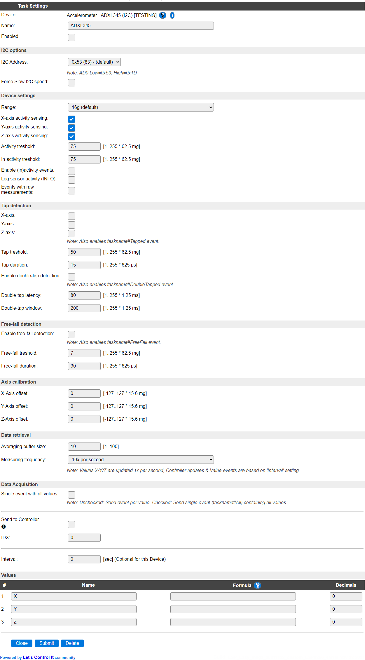
Name A unique name should be entered here.
Enabled The device can be disabled or enabled. When not enabled the device should not use any resources.
I2C Options
The available settings here depend on the build used. At least the Force Slow I2C speed option is available, but selections for the I2C Multiplexer can also be shown. For details see the I2C Bus page
I2C Address: The address the device is using. Some boards holding this chip offer an extra connection SD0 that can be used to select the address. The available addresses are 0x53 and 0x1D (secondary).
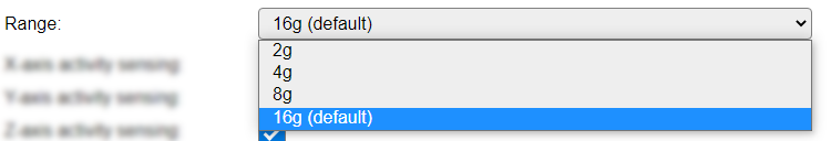
Device Settings
Range: The range determines the sensitivity and accuracy of the sensor, and the default is set to 16G as then the measuring resolution is 13 bit, while in lower ranges the resolution is 10 bit.
X/Y/Z-axis activity sensing: These 3 settings determine if sensing for that axis is to be used or not. If an axis is disabled, then the resulting Value will be 0.
Activity treshold: The minimum of movement required to include the activity in measurement. When setting too low, the sensor will be very instable, and cause many events. The treshold is configurable in steps of 62.5 milligram.
In-activity treshold: If the movement goes below this treshold, then measuring is stopped, and an In-activity event will be generated (if enabled).
Enable (in)activity events: When enabled will generate an event for each enabled axis if activity or in-activity state changes.
Log sensor activity (INFO): When enabled will log any activity or in-activity that is detected. The log is output at INFO level, so that level, or a more detailed level like DEBUG, must be enabled to be visible.
Events with raw measurements: When enabled wil, instead of a corrected, calculated and averaged measurement, output the raw measured value from the sensor. This is normally only used for debugging or testing purposes.
Tap detection
X/Y/Z-axis: When enabled will detect single-tap activity for the axis enabled. Be aware that even if the sensor is tapped in a clean X, Y or Z direction, still the other directions will most likely also be triggered. Enabling one of these axis will enable generation of a
taskname#Tappedevent, with 3 arguments for all 3 axis, providing the last measured X/Y/Z activity, or 0 when that axis activity is disabled.Tap treshold: The minimum acceleration required to cause a tap detected. Again this is measured in 62.5 milligram increments.
Tap duration: The minimum duration of a tap to be recognized as such. Configurable in 625 microsecond increments.
Enable double-tap detection: If Single-tap detection is enabled for any of the axis, then Double-tap can be detected as well. This will be generated as a
taskname#DoubleTapevent. Once a Double-tap is detected, no single-tap event will be generated for the same movement.Double-tap latency: The amount of time that has to pass between the 2 taps of a double-tap action. Configurable in 1.25 millisecond steps.
Double-tap window: The maximum time that may pass before the second of taps is to be registered as a double-tap. Configurable in 1.25 millisecond steps.
Free-fall detection
Enable free-fall detection: The sensor is able to detect if it is falling (free-fall), and can generate an event
taskname#FreeFallif it does. To enable that feature this checkbox should be checked.Free-fall treshold: To avoid false triggers, the treshold can be set before a movement is detected as free-fall. This can be set in 62.5 milligram increments.
Free-fall duration: The minimum time the sensor is falling before a free-fall event is generated can be configured in 625 microsecond increments.
Axis calibration
X/Y/Z-axis offset: Corrective values can be set to calibrate the sensor once it is mounted in its intended location. These values are similar to the measured values as presented. Available calibration range is -127 to 127.
Typically the raw values output by the sensor are scaled to 256/g. However this is when powering the chip at 2.5 Volt. When powering the chip with a higher voltage, like 3.3V, the sensitivity will slightly increase to roughly 280/g.
A different voltage will also create some offset in measured values. When operating at a supply voltage of VS = 3.3 V, the X- and Y-axis offset is typically 25 mg higher than at Vs = 2.5 V operation. The z-axis is typically 20 mg lower when operating at a supply voltage of 3.3 V than when operating at VS = 2.5 V.
The scale used for setting the offset is expressed in 15.6 mg per count. Thus when using a supply voltage of 3.3V, typical offsets are:
X- and Y-axis offset: -1 or -2
Z-axis offset: 1
Note
The values used as offset are roughly -0.25x the difference in measured values, since the measurements have a resolution of 3.9 mg and the units for the offset are in 15.6 mg.
Each individual chip may need different offsets. These differences can be caused by the assembly procedure, mechanical stress on the mounted chip, etc.
Calibration procedure
To calibrate the sensor in its intended position follow these steps:
Reset all calibration settings to 0.
Enable all axis that need to be calibrated in the Device settings section.
Set the Averaging buffer size to 10, and the Measuring frequency to 10x per second.
Uncheck Events with raw measurements. This setting should be left unchecked when expecting calibrated measurements using the sensor.
Set the Interval to 5 seconds.
Save the settings using the Submit button.
Place the sensor in its intended position.
Enable the sensor, if that wasn’t already set (can be done using the settings page or by sending a
TaskEnable,tasknamecommand).Wait for at least 30 seconds to stabilize the measurements.
Take note of the values for the X, Y and Z axis values, as presented on the Devices overview page.
For each axis to be calibrated, enter the X, or Y value(s) multiplied by -0.25 into the X- and Y-axis calibration fields.
The Z-axis value has a default deviation of -256 so that has to be used as the reference point. Add 256 to the noted Z-axis value to get the required Z-axis calibration value. (See “Axis Calibration” section above)
Restore any of the settings changed above to their original state.
Save the settings using the Submit button.
Validate that the measured values are now 0 with the sensor in its intended position.
NB: Instead of calibrating to 0 it is also possible to calibrate a defined offset, if that better fits the intended solution.
Tip:
Turning the sensor up-side-down and let it rest for a while may give a more reliable result in determining the true offset per axis.
For example -274 and 300 for one axis does show the true offset is: (-274 + 300) / 2 = 13.
This 13 is in units of 3.9 mg.
Thus the axis offset = -0.25 * 13 = -3
Output Configuration
(Added: 2022/11/22)
Each task value can be set to one of the following:
X/Y/Z RAW: The raw sensor reading per X, Y or Z axis
X/Y/Z (g): The reading converted back to g.
Pitch Angle: Rotation angle in the X/Z plane, thus rotating over the Y-axis. Like a plane with the nose pointing in the X-axis direction, which may point the nose down or up. Resp. descend or gaining altitude.
Roll Angle: Rotation angle over the X-axis. Like a plane which rotates such that one wing will go down and the other up, to make a left or right turn.
The unit for the angle output types can be in radians or degrees.
Due to the relative coarse axis offset calibration, the calculated angles may be off by 1.5 - 2 degree. The resolution of the Axis Calibration is roughly 2.55 - 2.8 degree, depending on the voltage supplied to the chip.
Note
The conversion to g is done by averaging the length of the vector setup by the X, Y and Z raw sensor readings.
We assume that on average the length of this vector must represent 1 g. Since this scaling factor can vary depending on the supply voltage, this averaging is done via an IIR filter.
When the axis offset isn’t perfect, a sensor which does not experience mechanical acceleration, may still show a value > 1.00 g. However this will gradually be corrected to 1.00 g.
Data retrieval
Averaging buffer size: The number of measurements that will be averaged before presenting it as Values. When set to 1, there is effectively no averaging.
Measuring frequency: The plugin supports 2 measuring frequencies, 10x per second or 50x per second. When using 50x per second, it will stabilize the measurements if the Averaging buffer size is also increased, f.e. to 50 or 100. This may increase the load on the ESP unit somewhat.
Data Acquisition
This group of settings are standard available configuration items.
Single event with all values: When this setting is enabled, all available values will be sent in a single event
<TaskName>#All, with all values in order as arguments to the event.Show derived values: When checked, the Devices overview page, and the
/jsonendpoint (used for updating the Devices overview page) will include any Derived values as defined. See theTaskValueSetDerivedandTaskValueSetPresentationcommands.Event & Log derived values: When checked, the Derived values will be generated as Events, to be handled in Rules, and sent to logging devices like the Syslog server and/or SD-card logging.
(The derived values options are only available if String variables feature is included in the build.)
Send to Controller: Select the Controller(s) to send the Values to, either on a
TaskRuncommand applied to the task, or on an Interval time action.
Send to Controller is only visible when one or more Controllers are configured.
Depending on the controller capabilities, some configuration settings may be shown:

All configured Controllers are shown here, including the enabled or disabled state (multiple Controllers can be enabled, only a single MQTT Controller can be enabled at one time!).
For each controller the user can select wether the data should be sent on each Interval (or explicit TaskRun).
For the Domoticz controllers the value index (IDX) has to be configured.
For some controllers, like Home Assistant/openHAB, there are extra options available.
Group: This represents the group id to combine all values from multiple tasks into a single grouped-device during MQTT AutoDiscovery. Groups, by design, can span multiple ESPEasy devices, if desired, as long as the Task/Valuename combinations are unique. If a group should only combine Tasks from a single ESPEasy unit, the group id should be unique across multiple ESPEasy units. The group description, default Group <n>, can be adjusted in Home Assistant. If the Group value matches the current Unit nr, the Unit name,
%sysname%, is used instead of Group <nr>.Retained: For MQTT Controllers, this setting can be enabled to send the values for the current task with the Retain flag set. The Publish Retain flag in the Controller settings will override this by sending all task values with Retain flag enabled.
Send derived: This checkbox determines if any configured Derived values should also be sent to the controller (and included in the AutoDiscovery if that’s available and enabled).
Resend MQTT Discovery: When checked, will start a resend of the MQTT Discovery process for this task after a random delay, when Submit is clicked, so any changed settings will be updated in the MQTT broker. This setting is only available if the controller is enabled, the Auto Discovery feature is available and enabled for the controller. This setting is not stored.
Other controllers, like f.e. FHEM HTTP, do not support additional settings besides the checkbox to enable sending the data.
Values
There are 3 values available for this sensor, with default names as provided. The number of decimals of the raw values is by default set to 0, as no decimals are provided from the measurement.
The default number of decimals for the values in g and the angles is set to 2 decimals.
(Added: 2022/11/22)
The pitch and roll values can also be used, even though they are not set as output values.
To use them in rules, on displays, etc. Use:
[taskname#pitch][taskname#roll]
With taskname being the name given to the task running this plugin.
Change log
Changed in version 2.0: …
added 2021-10-30 Initial release version.