Gyro - ITG3205
ITG3205 Gyro sensor
Plugin details
Type: Gyro
Name: ITG3205
Status ESP32: COLLECTION E
Status ESP8266: COLLECTION E
GitHub: _P119_ITG3205_Gyro.ino
Maintainer: tonhuisman
Used libraries: https://github.com/ikiselev/ITG3205 (Using a modified local copy)
Configuration
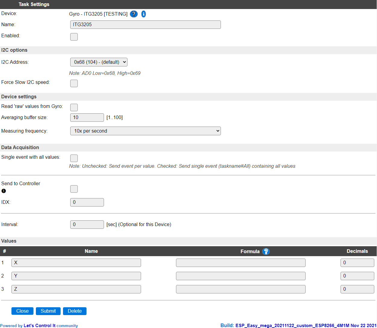
Task settings
Name The name of the task. This should be unique for all devices that are configured. (Initially empty)
Enabled For the device to work it has to be enabled. When checked, the device will be started as soon as the ESP starts. If desired, the device can also be enabled from f.e. a rule by using the
TaskEnable,<tasknr>orTaskEnable,<taskname>command, or disabled using the correspondingTaskDisable,<tasknr>|<taskname>commands.
I2C Options
The available settings here depend on the build used. At least the Force Slow I2C speed option is available, but selections for the I2C Multiplexer can also be shown. For details see the I2C Bus page
I2C Address: The address the device is using. The ITG3205 chip allows to select a secondary address by pulling the AD0 pin to high (3.3V) to select the secondary address. That address should then be selected here too. Not all available modules allow configuring the secondary address.
Device Settings
Read ‘raw’ values from Gyro When checked the reported values are not calibrated. This option is made available as the library provides it, but during testing the raw results didn’t seem very useful.
Normally, at startup of the plugin, a calibration is determined by reading 128 measurements, negating the result and averaging that per axis. This is then used to calibrate the actual measurements at every read by adding the calculated offset, and dividing the result by a manufacturer provided constant (14.375).
Averaging buffer size Defines the size of the averaging buffer. To provide more stable & smooth measurements, the results can be averaged by using a buffer size > 1. The maximum buffer size is 100, making the updates change quite slow. The default setting of 10 should provide stable results. Averaging can be disabled by setting the buffer size to 1.
Measuring frequency The measuring frequency determines the number of samples per second that are taken.
The available options:
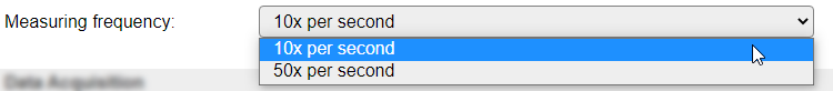
10x per second The default setting, can be used if the movement of the module is slow or medium fast.
50x per second Can be used if the movement of the module is fast, or a high update interval is needed, then the smoothing of the results can be enhanced by increasing the Averaging buffer size.
Data Acquisition
This group of settings are standard available configuration items.
Single event with all values: When this setting is enabled, all available values will be sent in a single event
<TaskName>#All, with all values in order as arguments to the event.Show derived values: When checked, the Devices overview page, and the
/jsonendpoint (used for updating the Devices overview page) will include any Derived values as defined. See theTaskValueSetDerivedandTaskValueSetPresentationcommands.Event & Log derived values: When checked, the Derived values will be generated as Events, to be handled in Rules, and sent to logging devices like the Syslog server and/or SD-card logging.
(The derived values options are only available if String variables feature is included in the build.)
Send to Controller: Select the Controller(s) to send the Values to, either on a
TaskRuncommand applied to the task, or on an Interval time action.
Send to Controller is only visible when one or more Controllers are configured.
Depending on the controller capabilities, some configuration settings may be shown:

All configured Controllers are shown here, including the enabled or disabled state (multiple Controllers can be enabled, only a single MQTT Controller can be enabled at one time!).
For each controller the user can select wether the data should be sent on each Interval (or explicit TaskRun).
For the Domoticz controllers the value index (IDX) has to be configured.
For some controllers, like Home Assistant/openHAB, there are extra options available.
Group: This represents the group id to combine all values from multiple tasks into a single grouped-device during MQTT AutoDiscovery. Groups, by design, can span multiple ESPEasy devices, if desired, as long as the Task/Valuename combinations are unique. If a group should only combine Tasks from a single ESPEasy unit, the group id should be unique across multiple ESPEasy units. The group description, default Group <n>, can be adjusted in Home Assistant. If the Group value matches the current Unit nr, the Unit name,
%sysname%, is used instead of Group <nr>.Retained: For MQTT Controllers, this setting can be enabled to send the values for the current task with the Retain flag set. The Publish Retain flag in the Controller settings will override this by sending all task values with Retain flag enabled.
Send derived: This checkbox determines if any configured Derived values should also be sent to the controller (and included in the AutoDiscovery if that’s available and enabled).
Resend MQTT Discovery: When checked, will start a resend of the MQTT Discovery process for this task after a random delay, when Submit is clicked, so any changed settings will be updated in the MQTT broker. This setting is only available if the controller is enabled, the Auto Discovery feature is available and enabled for the controller. This setting is not stored.
Other controllers, like f.e. FHEM HTTP, do not support additional settings besides the checkbox to enable sending the data.
Interval By default, Interval will be set to 0 sec. It is the frequency used to read the sensor values, averaged by the Averaging buffer, and send these to any Controller(s) configured for this device.
Values
The names for the values are initially set to a default name, but can be changed if desired. Also, a formula can be entered to re-calculate the value before display/sending to a controller, and the number of decimals can be changed, but these have been set to 0 as the sensor does not provide any decimals itself. Using a formula can cause decimals to be introduced, so this should then be adjusted.
Change log
Added in version 2.0: …
added 2021-10-28 Initial version.