Energy (DC) - INA3221/INA226/INA228/INA231/INA260
I2C DC Voltage/Current sensor
Plugin details
Type: Energy (DC)
Name: INA3221/INA226/INA228/INA231/INA260
Status ESP32: ENERGY
Status ESP8266: ENERGY
GitHub: P132_INA3221.ino
Maintainer: tonhuisman
Used libraries: https://github.com/Zanduino/INA (small adjustments applied)
Description
This plugin had support for INA3221 only, and has been extended with support for more types of INA sensors, though this extension is by default not enabled for ESP8266 builds. That version is available in Original documentation.
Support for INAxxx DC Voltage/Current/Power measurement sensors, INA3221, INA219, INA226, INA228, INA230, INA231 and INA260.
Existing plugin settings are forward compatible with the new settings.
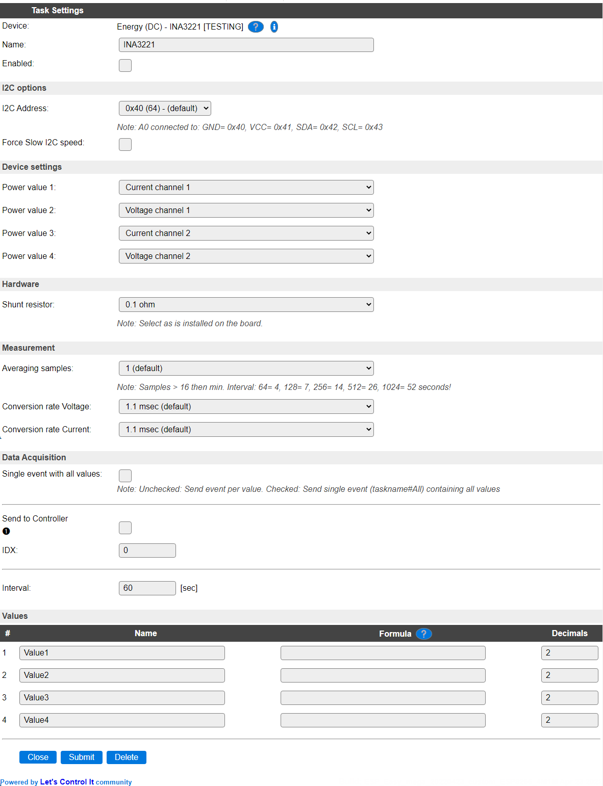
Configuration
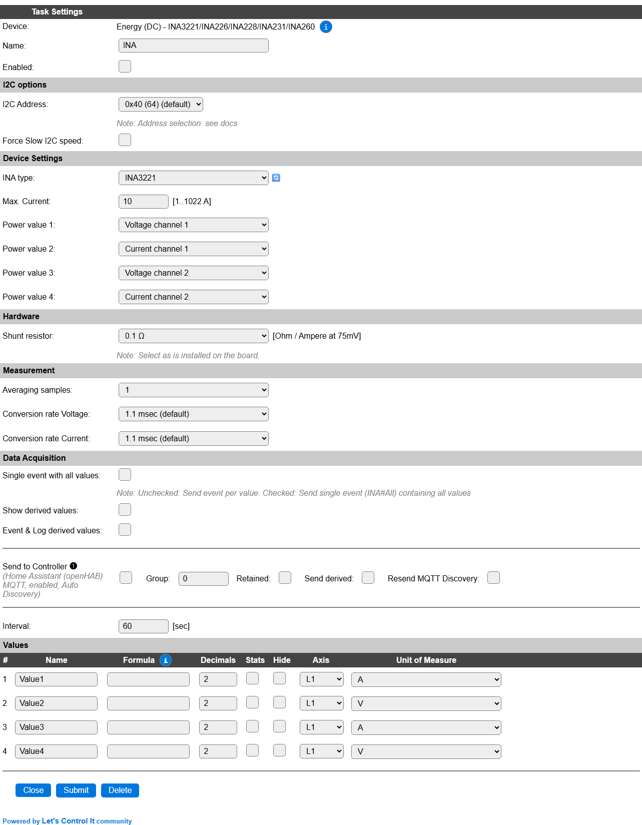
Name A unique name should be entered here.
Enabled The device can be disabled or enabled. When not enabled the device should not use any resources.
I2C Options
The available settings here depend on the build used. At least the Force Slow I2C speed option is available, but selections for the I2C Multiplexer can also be shown. For details see the I2C Bus page
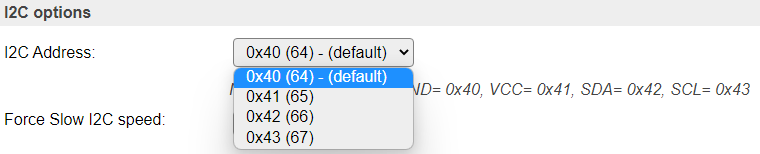
I2C Address: The address the sensor is using. The different addresses can be selected by connecting the appropriate signal to
A0andA1when available. Often also documented on the board.
For INA3221 the range is limited to the first 4 addresses, for other INA types, 16 addresses are available:
Selectable I2C addresses:
Address |
A0 |
A1 |
|
|---|---|---|---|
0x40 |
GND |
GND |
|
0x41 |
VS+ |
GND |
|
0x42 |
SDA |
GND |
|
0x43 |
SCL |
GND |
|
0x44 |
GND |
VS+ |
|
0x45 |
VS+ |
VS+ |
|
0x46 |
SDA |
VS+ |
|
0x47 |
SCL |
VS+ |
|
0x48 |
GND |
SDA |
|
0x49 |
VS+ |
SDA |
|
0x4A |
SDA |
SDA |
|
0x4B |
SCL |
SDA |
|
0x4C |
GND |
SCL |
|
0x4D |
VS+ |
SCL |
|
0x4E |
SDA |
SCL |
|
0x4F |
SCL |
SCL |
Device Settings
INA type: Select the INA chip type you want to connect. This has to match with what is auto-detected by the library. As INA231 is often recognized as an INA226, this is an accepted alternative. And also the other way around. The difference is only in the specifications of the chip, from software side they are practically identical.
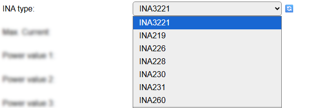
NB: INA219 is already supported by Energy (DC) - INA219 but is still added here as it is supported by the used library.
Max. Current: Configure the max. to be expected/measured current, so the library can optimize the configuration combined with the Conversion rate and Shunt resistor settings, below. Range is
1..1022 A, default set at10.Power value 1..4: Most INA types have 3
Power valuesavailable, only INA3221 has 9 values available. As a plugin only has 4 available output values, here we have to select what output receives what measured value.
Available options for INA3221 are:
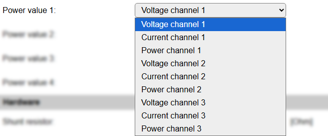
Voltage channel 1..3: Measure the voltage from channel 1..3.
Current channel 1..3: Measure the current from channel 1..3.
Power channel 1..3: Calculated power from channel 1..3.
Other INA types the available options are:
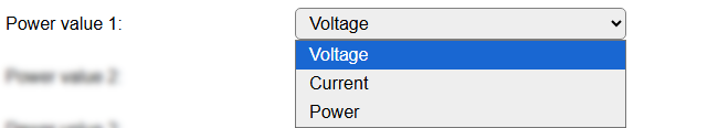
Voltage: Measure the voltage in V.
Current: Measure the current in mA.
Power: Measure the power in mW. (Needs
VBusto be connected to the sensor)
Hardware
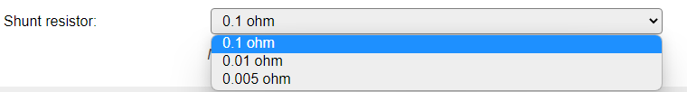
Shunt resistor: Here you can select the resistance or shunt that is used, this should match closely with the Max. Current setting:
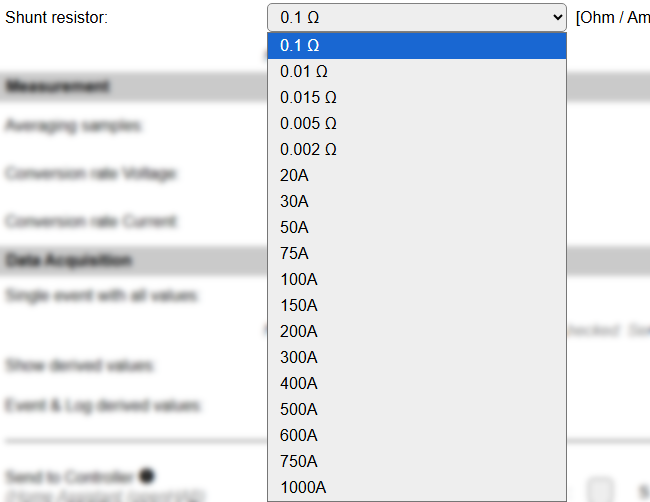
On many boards a shunt resistor is installed, that has one of the available resistance values. When larger currents are to be measured, an external shunt is mounted, and the sensor is connected via the Kelvin Connection that are available on the shunt (the small screws). The pre-installed shunt resistor must then be removed from the sensor-board, to avoid possible damage. These shunt are mostly specified for the current at wich a measurable voltage of 75 mV is reached. Some preselected values, up to the max. range of the sensor of ca. 1022 A, are selectable.
NB: INA260 has an internal shunt resistor of 2 mOhm, so when selecting that INA type, the setting is fixed at that value.
Measurement
Averaging samples: To increase the accuracy of measurements, the chip allows to take the average value for a set of samples. The desired number of samples can be selected in this setting, default: 1.
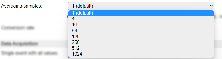
This setting is not available for INA219, as this chip has the Averaging samples setting combined with the Conversion rate.
When combining a higher number of samples with a longer Conversion rate, taking all possible measurements will require more time, affecting the Interval that would be feasible for a reliable measurement. The worst-case scenarios (maximum Conversion rate settings) have been calculated, and are shown as a note below this setting.
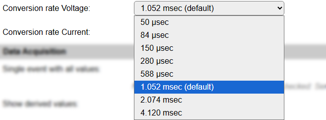
Conversion rate Voltage/Current: To change the accuracy of measurements, a different conversion rate can be selected. Lowering the conversion rate will decrease the accuracy, and allow a higher sampling frequency, but as the measurements are read at a smallest Interval of 1 second, there isn’t much use in lowering the conversion rate. When increasing the conversion rate, accuracy will increase, but, also depending on the Averaging samples configured, increases the time it takes to complete all measurements. (Calculation formula below).
There are separate Conversion rate settings for the Voltage and Current measurements, as that’s available in the chip.
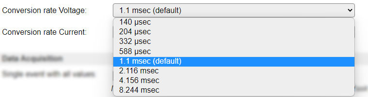
To calculate the minimally required Interval setting for the task, this formula can be used:
(3 * Averaging samples * Conversion rate Voltage) + (3 * Averaging samples * Conversion rate Current), and round that up to a seconds value.Example: (Worst case) 3 * 1024 * 0.008244 + 3 * 1024 * 0.008244 = 50.65 seconds => ~51 minimum Interval.Example: (Default case) 3 * 1 * 0.00144 + 3 * 1 * 0.00144 = 0.008 seconds => 1 minimum Interval.
For INA219 a different Conversion rate selector is available:
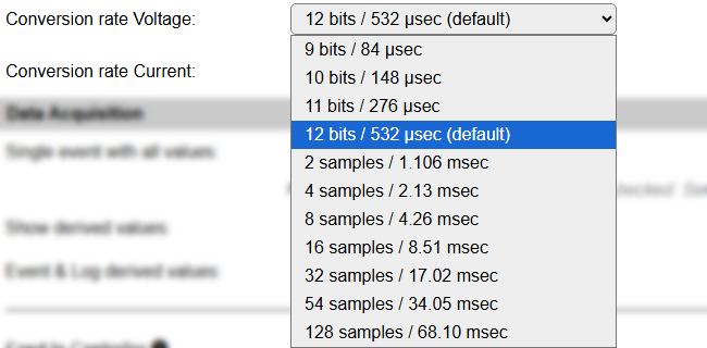
Also for INA228 a different Conversion rate selector is available:
Data Acquisition
This group of settings are standard available configuration items.
Single event with all values: When this setting is enabled, all available values will be sent in a single event
<TaskName>#All, with all values in order as arguments to the event.Show derived values: When checked, the Devices overview page, and the
/jsonendpoint (used for updating the Devices overview page) will include any Derived values as defined. See theTaskValueSetDerivedandTaskValueSetPresentationcommands.Event & Log derived values: When checked, the Derived values will be generated as Events, to be handled in Rules, and sent to logging devices like the Syslog server and/or SD-card logging.
(The derived values options are only available if String variables feature is included in the build.)
Send to Controller: Select the Controller(s) to send the Values to, either on a
TaskRuncommand applied to the task, or on an Interval time action.
Send to Controller is only visible when one or more Controllers are configured.
Depending on the controller capabilities, some configuration settings may be shown:

All configured Controllers are shown here, including the enabled or disabled state (multiple Controllers can be enabled, only a single MQTT Controller can be enabled at one time!).
For each controller the user can select wether the data should be sent on each Interval (or explicit TaskRun).
For the Domoticz controllers the value index (IDX) has to be configured.
For some controllers, like Home Assistant/openHAB, there are extra options available.
Group: This represents the group id to combine all values from multiple tasks into a single grouped-device during MQTT AutoDiscovery. Groups, by design, can span multiple ESPEasy devices, if desired, as long as the Task/Valuename combinations are unique. If a group should only combine Tasks from a single ESPEasy unit, the group id should be unique across multiple ESPEasy units. The group description, default Group <n>, can be adjusted in Home Assistant. If the Group value matches the current Unit nr, the Unit name,
%sysname%, is used instead of Group <nr>.Retained: For MQTT Controllers, this setting can be enabled to send the values for the current task with the Retain flag set. The Publish Retain flag in the Controller settings will override this by sending all task values with Retain flag enabled.
Send derived: This checkbox determines if any configured Derived values should also be sent to the controller (and included in the AutoDiscovery if that’s available and enabled).
Resend MQTT Discovery: When checked, will start a resend of the MQTT Discovery process for this task after a random delay, when Submit is clicked, so any changed settings will be updated in the MQTT broker. This setting is only available if the controller is enabled, the Auto Discovery feature is available and enabled for the controller. This setting is not stored.
Other controllers, like f.e. FHEM HTTP, do not support additional settings besides the checkbox to enable sending the data.
Values
The Values available for this sensor, are named Value1 through Value4, and can be adjusted as desired. The Formula field can be used to recalculate the shown results. Decimals should probably be set too.
Per Value is a Stats checkbox available, that when checked, gathers the data and presents recent data in a graph, as described here: Task Value Statistics:
Original documentation
Description
The INA3221 Voltage/Current sensor can be used to measure voltage and/or current for DC input, up to 26V. It has 3 separate channels available.
It can be used to replace the Energy (DC) - INA219, except that the I2C protocol isn’t directly compatible, so it is not a drop-in replacement.
Configuration
Name A unique name should be entered here.
Enabled The device can be disabled or enabled. When not enabled the device should not use any resources.
I2C Options
The available settings here depend on the build used. At least the Force Slow I2C speed option is available, but selections for the I2C Multiplexer can also be shown. For details see the I2C Bus page
I2C Address: The address the sensor is using. The different addresses can be selected by connecting the appropriate signal to A0. Often also documented on the board.
Device Settings
Power value 1..4: As a plugin only has 4 available output values and the sensor has 6 values available, here we have to select what output receives what measured value.
Available options are:
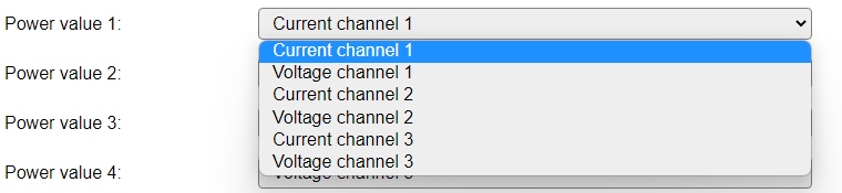
Current channel 1..3: Measure the current from channel 1..3.
Voltage channel 1..3: Measure the voltage from channel 1..3.
NB: To get all measured values, an extra Task can be configured to provide the measurements not handled in the current task, or you could f.e. configure separate tasks for Voltage and Current measurements. These tasks shouldn’t interfere, assuming both get the same configuration settings for Shunt resistor, Averaging samples and Conversion rate Voltage / Conversion rate Current.
Hardware
Shunt resistor: As there are different hardware configurations available for the board, using different shunt resistor values, here you can select the value that is present on the board used.
Measurement
Averaging samples: To increase the accuracy of measurements, the chip allows to take the average value for a set of samples. The desired number of samples can be selected in this setting, default: 1.
When combining a higher number of samples with a longer Conversion rate, taking all possible measurements will require more time, affecting the Interval that would be feasible for a reliable measurement. The worst-case scenarios (maximum Conversion rate settings) have been calculated, and are shown as a note below this setting.
Conversion rate Voltage/Current: To change the accuracy of measurements, a different conversion rate can be selected. Lowering the conversion rate will decrease the accuracy, and allow a higher sampling frequency, but as the measurements are read at a smallest Interval of 1 second, there isn’t much use in lowering the conversion rate. When increasing the conversion rate, accuracy will increase, but, also depending on the Averaging samples configured, increases the time it takes to complete all measurements. (Calculation formula below).
There are separate Conversion rate settings for the Voltage and Current measurements, as that’s available in the chip.
To calculate the minimally required Interval setting for the task, this formula can be used:
(3 * Averaging samples * Conversion rate Voltage) + (3 * Averaging samples * Conversion rate Current), and round that up to a seconds value.Example: (Worst case) 3 * 1024 * 0.008244 + 3 * 1024 * 0.008244 = 50.65 seconds => ~51 minimum Interval.Example: (Default case) 3 * 1 * 0.00144 + 3 * 1 * 0.00144 = 0.008 seconds => 1 minimum Interval.
Data Acquisition
This group of settings are standard available configuration items.
Single event with all values: When this setting is enabled, all available values will be sent in a single event
<TaskName>#All, with all values in order as arguments to the event.Show derived values: When checked, the Devices overview page, and the
/jsonendpoint (used for updating the Devices overview page) will include any Derived values as defined. See theTaskValueSetDerivedandTaskValueSetPresentationcommands.Event & Log derived values: When checked, the Derived values will be generated as Events, to be handled in Rules, and sent to logging devices like the Syslog server and/or SD-card logging.
(The derived values options are only available if String variables feature is included in the build.)
Send to Controller: Select the Controller(s) to send the Values to, either on a
TaskRuncommand applied to the task, or on an Interval time action.
Send to Controller is only visible when one or more Controllers are configured.
Depending on the controller capabilities, some configuration settings may be shown:
All configured Controllers are shown here, including the enabled or disabled state (multiple Controllers can be enabled, only a single MQTT Controller can be enabled at one time!).
For each controller the user can select wether the data should be sent on each Interval (or explicit TaskRun).
For the Domoticz controllers the value index (IDX) has to be configured.
For some controllers, like Home Assistant/openHAB, there are extra options available.
Group: This represents the group id to combine all values from multiple tasks into a single grouped-device during MQTT AutoDiscovery. Groups, by design, can span multiple ESPEasy devices, if desired, as long as the Task/Valuename combinations are unique. If a group should only combine Tasks from a single ESPEasy unit, the group id should be unique across multiple ESPEasy units. The group description, default Group <n>, can be adjusted in Home Assistant. If the Group value matches the current Unit nr, the Unit name,
%sysname%, is used instead of Group <nr>.Retained: For MQTT Controllers, this setting can be enabled to send the values for the current task with the Retain flag set. The Publish Retain flag in the Controller settings will override this by sending all task values with Retain flag enabled.
Send derived: This checkbox determines if any configured Derived values should also be sent to the controller (and included in the AutoDiscovery if that’s available and enabled).
Resend MQTT Discovery: When checked, will start a resend of the MQTT Discovery process for this task after a random delay, when Submit is clicked, so any changed settings will be updated in the MQTT broker. This setting is only available if the controller is enabled, the Auto Discovery feature is available and enabled for the controller. This setting is not stored.
Other controllers, like f.e. FHEM HTTP, do not support additional settings besides the checkbox to enable sending the data.
Values
The Values available for this sensor, are named Value1 through Value4, and can be adjusted as desired. The Formula field can be used to recalculate the shown results.
Change log
Changed in version 2.0: …
added 2025-12-27 Extended adding INA219, INA226, INA228, INA230, INA231 and INA260.
added 2022-04-23 Initial release version.