Environment - AS3935 Lightning Detector
AS3935 Franklin Lightning Sensor IC / Lightning Detector
Plugin details
Type: Environment
Name: AS3935 Lightning Detector
Status ESP32: CLIMATE B
Status ESP8266: .
GitHub: P169_AS3935_LightningDetector.ino
Maintainer: TD-er
Used libraries: https://bitbucket.org/christandlg/as3935mi/src/master/
Description
The AS3935 is a programmable fully integrated Lightning Sensor IC that detects the presence and approach of potentially hazardous lightning activity in the vicinity and provides an estimation on the distance to the head of the storm. The embedded lightning algorithm checks the incoming signal pattern to reject the potential man-made disturbers.
Highlights:
Can detect lightning storm activity within a 40 km range.
Provides distance estimation to the head of the storm.
Detects both cloud-to-ground and intra-cloud (cloud-to-cloud) flashes.
Internal algorithm to reject false disturbances.
This chip can be found on a number of boards, like this one from DFRobot.

(Image (c) DFRobot)
Calibration Procedure
The AS3935 sensor is using 3 separate oscillators:
LCO: 500 kHz resonance frequency used to tune the antenna.
SRCO: Typ. ~1.1 MHz signal used internally in the sensor.
TRCO: Typ. 32768 Hz signal used internally in the sensor.
The LCO oscillator needs to be calibrated within 3.5% of its intended 500 kHz. For this the sensor can connect upto 15 tuning capacitors of 8 pF parallel to another capacitor to tune the resonance frequency of the antenna to 500 kHz.
The frequency of all of these three oscillators depends on environmental factors like temperature, but also the presence of other materials close to the antenna.
The LCO calibration is performed by feeding the LCO clock via some divisor to a GPIO pin on the ESP board. This signal is then measured several times to find the best tuning capacitor.
By default this LCO calibration does a quick test with antenna capacitor 0 and 15 and then computes the most likely capacitor.
This candidate and its neighbors are then measured for a longer period (about 30 msec) to reduce the error in measurement.
When the checkbox for “Slow LCO Calibration” is checked, each antenna capacitor is tested for about 30 msec. This may improve the accuracy and the success rate of the calibration.
Below the calibration charts of a quick and slow LCO calibration of the same sensor:
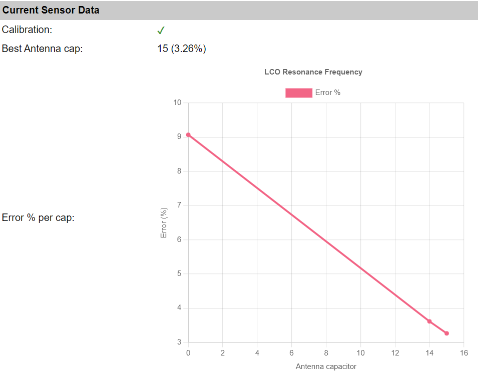

As can be seen, both were successful in calibrating the resonance frequency within 3.5% of 500 kHz.
However, the best one on this specific board and setup is antenna capacitor 15, which is the last one. So in this specific setup, it is very well possible the calibration may fail when some external factor changes. (e.g. temperature)
For setups like these, where the best option is close to the edge of the adjustable range, it is best to check the checkbox “Tolerate out-of-range calibration”. This way the calibration will not be considered failed when the tolerance ends up slightly above 3.5%.
On the other hand, if the best calibration is significantly further off from the optimal 500 kHz, there is something wrong with the setup.
For example:
Metal parts mounted close to the antenna.
Noisy environment. (See also the reported noise level, as this should be around 2 or 3)
Unstable power supplied to the sensor.
See the Wiring section below for more tips.
Note
The SRCO and TRCO frequencies are calibrated after the LCO frequency. When the LCO frequency is off by too much, the calibration of the other two may also fail.
Sensor Operating Modes
The sensor can signal some event via the IRQ pin to ESPEasy. This pin state remains high until the sensor state is read.
Power-Down Mode
This mode is set when ESPEasy enters deep sleep to reduce current consumption (typ 1μA).
Listening Mode
The sensor will be operating in this mode for most of the time. Typical current consumption in this mode is about 60μA. (70μA when the internal voltage regulator is enabled)
There will always be some noise picked up by the antenna. When this noise exceeds the set noise floor, the sensor will pull the IRQ pin high and return to “Listening mode”.
ESPEasy will then try to increase the noise floor.
After 15 seconds of not receiving any interrupt signal, ESPEasy will try to lower the noise floor.
Every time the set watchdog threshold is passed, the sensor will enter “Signal Validation” mode.
Signal Validation Mode
Typical current consumption in this mode is about 350μA.
In case the incoming signal does not have the shape characteristic to lightning, the signal validation fails and the event is classified as disturber.
If the signal is classified as disturber the chip immediately aborts the signal processing and goes back into the “Listening Mode”. Otherwise, the energy calculation is performed and the distance estimate provided.
Note
The calculated energy does not reflect any physical unit of measure. It is just a number. However it seems the sensor does use it internally to estimate the distance.
The received signal of a typical lightning strike consists of 3 .. 4 pulses about 40 msec apart.
According to the datasheet, the sensor needs roughly 1 second to classify an event as a lightning strike. However tests have shown the sensor might be able to classify _some_ lightning strikes in as little as 250 msec.
If the classification takes longer than 1.5 seconds, it will be classified as a disturber.
This implies the practial shortest time span between two lightning strikes that the sensor can resolve is approximately one second.
Note
Sometimes during intense thunderstorms there might be several lightning strikes in short succession. This sensor might classify those as disturbances as the total evaluation time might exceed 1.5 seconds.
As soon as the event has been classified, the sensor will return to “Listening Mode”.
Signal Validation Parameters
During the signal validation phase the shape of the incoming signal is analyzed. The sensor can differentiate between signals that show the pattern characteristic of lightning strikes and man-made disturbers such as random impulses.
Noise Floor
Range: 0 .. 7 (default: 2)
The noise floor acts as a threshold to differentiate real signals from noise.
When an interrupt signal for “noise floor threshold exceeded” is received, ESPEasy will increase the noise floor.
Watchdog
Range: 0 .. 15 (default: 2)
This sets the duration for a signal to last before entering “Signal Validation” mode.
Spike Rejection
Range: 0 .. 15 (default: 2)
Can be used to increase the robustness against false alarms from such disturbers. Larger values correspond to more robust disturber rejection, yet with the drawback of a decrease in detection efficiency.
When an “disturber detected” event is triggered, ESPEasy will try to increase either the Spike Rejection setting or Watchdog.
AFE gain and Energy level
The AS3935 sensor does have an amplifier with an adjustable gain factor which amplifies the incoming signal. This amplified signal is then used to estimate the “Energy” value.
Tests have shown the AS3935 sensor does use a lookup table to estimate the distance based on this energy level.
Dynamic Adjustment
ESPEasy does dynamically change these three settings. Upon interrupt signals for either noise floor exceeded or disturbance detected, these will be increased.
After 15 seconds ESPEasy will try to lower these values again to get as close as possible to the optimal settings.
Lightning Threshold
Values: 1, 5, 9, 16 (default: 1)
This set minimum number of lightning events counted within 15 minutes must occur before the first “Lightning detected” interrupt is sent. Once this threshold is passed, the sensor will resume its normal interrupt handling with an interrupt per detected lightning.
This internal count will also be cleared when the internal statistics are cleared or when the sensor is put to sleep. (when the ESPEasy task is ended, the sensor is put to sleep)
Wiring
This sensor can be used via SPI or I2C.
For ESPEasy it needs to be wired for I2C:
SIpin (“Select Interface”) must be pulled high.MOSIpin is I2C SDA.SCLpin is I2C SCL.A1andA0pulled high for the default address of0x03.
Apart from the I2C connection, there is an IRQ signal which must also be connected to the ESP board.
This IRQ signal is used to calibrate the sensor as well as to signal the ESP about some changed condition like a detected lightning strike or noise disturbances.
Board Specific
Some boards already have resistors present to pull the unused pins high or low where needed and are default set for I2C.
For example 8-pin brown or purple boards with GY-AS3935 written on the back is default configured for I2C with address 0x03.
Other boards like a slightly larger 11-pin purple board with WCMCU-3935 written on the board,
might need to have the unused pins (CS & MISO) explicitly pulled to GND.
The EN-V pin should be pulled high.
Power Supply and Noise
This sensor is quite sensitive to noise in its direct surroundings. Especially signals around 500 kHz will cause this sensor to perform significantly worse.
This sensor needs to have its resonance frequency calibrated within 3.5% of 500 kHz.
Some tips:
Keep DC/DC converters and other power supplies away from this sensor.
Keep smart phone and smart watch displays away from the sensor.
Add some 100 uF … 220 uF capacitor close to the power supply pins of the sensor.
Do not use any metal close to the antenna of the sensor as this will change the antenna resonance frequency.
Use short wires.
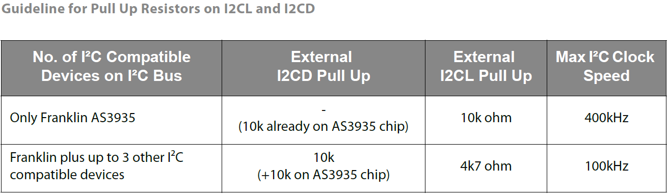
Lower I2C clock frequency to 100 kHz for all I2C devices on this ESPEasy board.
Lower I2C clock frequency on devices within a few meters from this sensor. (Explicitly stay away from 500 kHz)
Do not leave unused pins ‘floating’. Either pull them to 3V3 or GND.
Orientation of the antenna is not really important to measure lightning strikes, since lightning is not discharging straight, but in a zigzag pattern and the distance is very far away. However the orientation of the antenna can have an effect on the noise picked up from nearby sources.
The sensor chip does have an internal voltage regulator.
On some boards, this regulator can be enabled by pulling the EN-V or EN_VREG pin high (if made availabe on the board).
Onboard voltage regulator:
Enabled:
EN_VREGpin high,VREGvia 1uF to GND. Supply voltage range is 2.4V to 5.5VDisabled:
EN_VREGpin low,VREGconnected to VDD pin. Supply voltage range is 2.4V to 3.6V
With the onboard voltage regulator enabled, the current consumption will be slight higher. But the supplied voltage to the sensor will be more stable.
See the datasheet pages 15 and 16 for more information.


Configuration

Name: Required by ESPEasy, must be unique among the list of available devices/tasks.
Enabled: The device can be disabled or enabled. When not enabled the device should not use any resources.
I2C options
I2C Address: The device supports 83 addresses, and by default comes configured for address
0x03.
Available addresses are in the range 0x01 to 0x03.
The available I2C settings here depend on the build used. At least the Force Slow I2C speed option is available, but selections for the I2C Multiplexer can also be shown. For details see the I2C Bus page
Device Settings
IRQ: Configure the GPIO pin on the ESP board connected to the IRQ pin of the sensor. This pin is used for both the antenna calibration as well as to notify the ESP board of any lightning strike or detected disturbance.
Lightning Threshold: Minimum number of detected strikes in 15 minutes to let the sensor trigger the IRQ pin.
Mode: Set the Analog Front-End (AFE) gain for typical indoor/outdoor use case.
Ignore Disturbance: The sensor may trigger the IRQ pin to signal a lightning strike, high noise or detected disturbances. With “Ignore Disturbance” checked, this last one is ignored.
Current Sensor Data
Data Acquisition
This group of settings are standard available configuration items.
Single event with all values: When this setting is enabled, all available values will be sent in a single event
<TaskName>#All, with all values in order as arguments to the event.Show derived values: When checked, the Devices overview page, and the
/jsonendpoint (used for updating the Devices overview page) will include any Derived values as defined. See theTaskValueSetDerivedandTaskValueSetPresentationcommands.Event & Log derived values: When checked, the Derived values will be generated as Events, to be handled in Rules, and sent to logging devices like the Syslog server and/or SD-card logging.
(The derived values options are only available if String variables feature is included in the build.)
Send to Controller: Select the Controller(s) to send the Values to, either on a
TaskRuncommand applied to the task, or on an Interval time action.
Send to Controller is only visible when one or more Controllers are configured.
Depending on the controller capabilities, some configuration settings may be shown:

All configured Controllers are shown here, including the enabled or disabled state (multiple Controllers can be enabled, only a single MQTT Controller can be enabled at one time!).
For each controller the user can select wether the data should be sent on each Interval (or explicit TaskRun).
For the Domoticz controllers the value index (IDX) has to be configured.
For some controllers, like Home Assistant/openHAB, there are extra options available.
Group: This represents the group id to combine all values from multiple tasks into a single grouped-device during MQTT AutoDiscovery. Groups, by design, can span multiple ESPEasy devices, if desired, as long as the Task/Valuename combinations are unique. If a group should only combine Tasks from a single ESPEasy unit, the group id should be unique across multiple ESPEasy units. The group description, default Group <n>, can be adjusted in Home Assistant. If the Group value matches the current Unit nr, the Unit name,
%sysname%, is used instead of Group <nr>.Retained: For MQTT Controllers, this setting can be enabled to send the values for the current task with the Retain flag set. The Publish Retain flag in the Controller settings will override this by sending all task values with Retain flag enabled.
Send derived: This checkbox determines if any configured Derived values should also be sent to the controller (and included in the AutoDiscovery if that’s available and enabled).
Resend MQTT Discovery: When checked, will start a resend of the MQTT Discovery process for this task after a random delay, when Submit is clicked, so any changed settings will be updated in the MQTT broker. This setting is only available if the controller is enabled, the Auto Discovery feature is available and enabled for the controller. This setting is not stored.
Other controllers, like f.e. FHEM HTTP, do not support additional settings besides the checkbox to enable sending the data.
Interval By default, Interval will be set to 0 sec. The data will be collected and optionally sent to any configured controllers using this interval. When an output value is changed, the data will be sent to any configured controller, and an event will also be generated when the Rules are enabled (Tools/Advanced).
Values
In selected builds, per Value is a Stats checkbox available, that when checked, gathers the data and presents recent data in a graph, as described here: Task Value Statistics:
Commands available
Command Syntax |
Extra information |
|---|---|
|
Clear statistics in the sensor, like lightning strike counts and intermediate values used to estimate the distance of the storm front. |
|
Perform calibration of all oscillators in the sensor. |
|
Set the AFE gain to given value.
Input can either be the internal sensor register value of |
|
Set the Noise Floor threshold to given value. |
|
Set the Watchdog threshold to given value. |
|
Set Spike Rejection threshold to given value. |
Get Config Values
Config value |
Information |
|---|---|
|
Returns the current set Noise Floor threshold of the sensor. |
|
Returns the current set Watchdog threshold of the sensor. |
|
Returns the current set Spike Rejection threshold of the sensor. |
|
Returns the current active AFE gain factor of the sensor. ( |
Change log
Changed in version 2.0: …
added 2024-05-24 Initial release version.